
Adaptive machine tool for grinding and polishing complex surfaces
A technology for processing machine tools and complex curved surfaces. It is used in grinding machines, metal processing equipment, grinding/polishing equipment, etc. It can solve problems such as low processing efficiency, achieve high processing efficiency, reduce repeated positioning errors, and improve efficiency.
- Summary
- Abstract
- Description
- Claims
- Application Information
AI Technical Summary
Problems solved by technology
Method used
Image

Examples
Embodiment approach 1
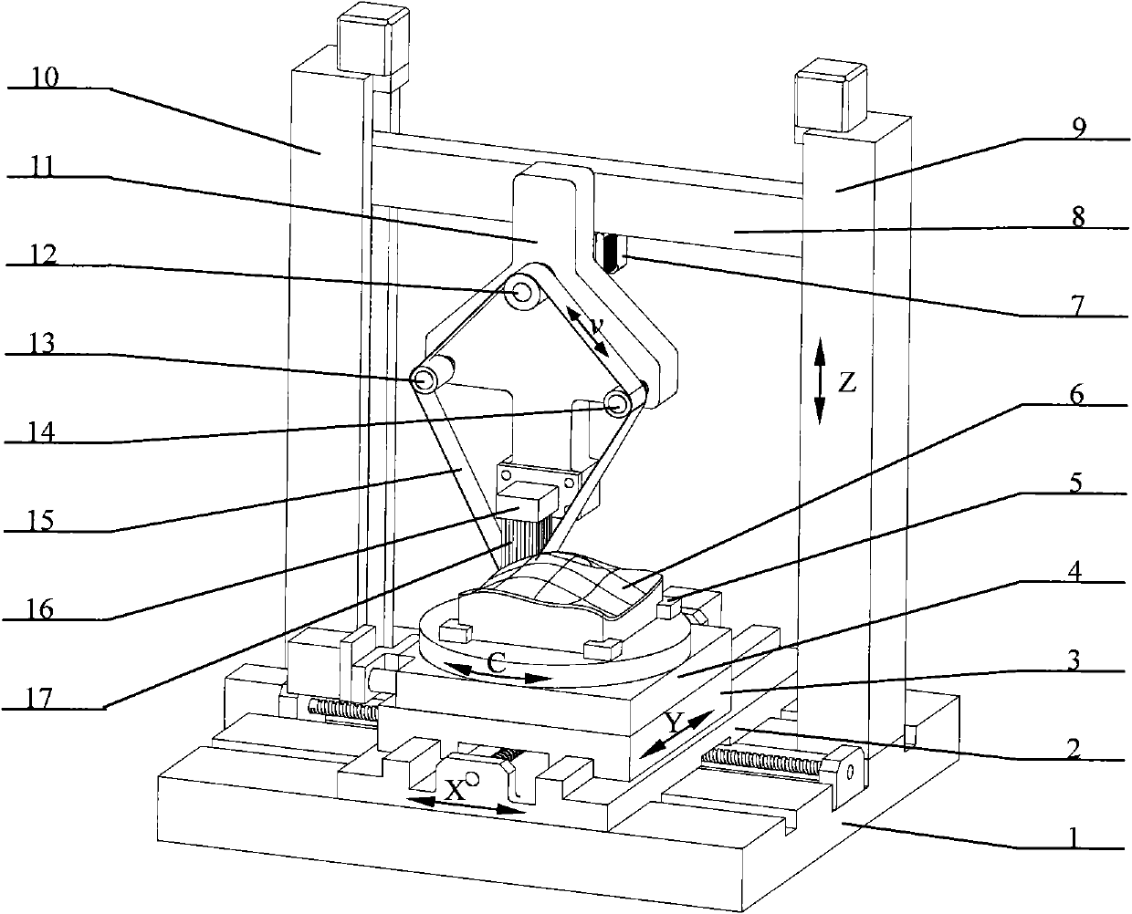
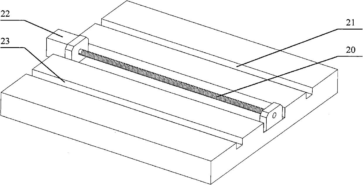
[0045] The overall structure of the program is as follows figure 1 As shown, the base 1, the left column 10, and the right column 9 form a fixed platform; the upper slide 3 and the lower slide 2 are horizontally distributed, and under the action of the upper slide motor 25 and the lower slide motor 22, respectively, they move along the lower slide 2 and the base 1 move longitudinally and laterally; the rotary table 4 is fixed on the upper slide 3, and the rotary table 4 can rotate around its axis; the workpiece 6 is fixed on the rotary table by clamping the positioning block 5 4, the rotary table 4 drives the workpiece 6 to rotate, so that the workpiece 6 is in a suitable processing position relative to the tool head; the horizontal feed movement of the workpiece 6 is provided by the horizontal movement of the upper slide 3 and the lower slide 2; the beam 8. The left column motor 38 and the right column motor 34 drive the Z-axis vertical movement along the left column 10 and t...
Embodiment approach 2
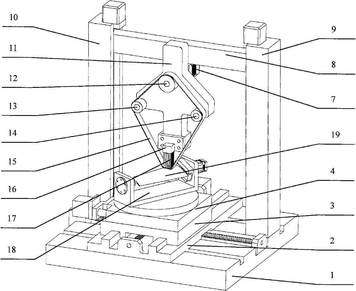
[0053] The overall structure of the program is as follows figure 2 As shown, the scheme's overall machine tool configuration, grinding and polishing tool system structure and working principle, tool feeding system, vertical and horizontal two-dimensional movement of the workpiece in the horizontal plane, and the realization of rotation around the Z axis are the same as those of the implementation scheme. totally agree.
[0054] The difference from Embodiment 1 is that the turning fixture 18 is installed on the rotary table 4, and the turning fixture 18 can drive the complex workpiece 19 to turn a certain angle to process the other surface after processing one surface of the complex part requiring multi-face machining. Sequentially rotating until all surfaces have been machined, in effect flipping the fixture 18 provides a rotational movement about the Y axis.
PUM
 Abstract
Description
Claims
Application Information