
Axial flow fan propeller

A fan impeller, axial flow technology, used in mechanical equipment, non-variable capacity pumps, machines/engines, etc., can solve the problems of difficult drafting, high cost of precision casting molds, and difficult replacement, and achieve reliability and processing. The effect of improving accuracy, reducing production costs and extending service life

Inactive Publication Date: 2012-07-25
NORTHWESTERN POLYTECHNICAL UNIV
View PDF0 Cites 1 Cited by
  • Summary
  • Abstract
  • Description
  • Claims
  • Application Information

AI Technical Summary

Problems solved by technology

The shortcomings of the split processing method are: (a) Since a group of multiple blades are welded on the blade wheel, this involves the consistent welding positioning of multiple blades, so it is not easy to make the welding positioning of multiple blades accurate, As a result, the design performance of the fan will be reduced, such as the reduction of fan efficiency and fan ventilation; (b) the welding process is difficult to ensure the welding strength and consistency of each blade; (c) when a blade is damaged, it is difficult to repair the blade on the fan site. replace
[0005] The overall processing method is to integrally cast a group of blades and blade discs. Although this method can achieve consistent positioning of multiple blades in a group on the blade disc, the overall processing method has caused other problems. Insufficient, manifested as: (a) because a group of multiple blades have three-dimensional overlapping parts on the blade wheel, it is difficult to manufacture the mold for integral casting, especially difficult to draft during the casting process; (b) for blades and The overall casting of the blade wheel needs to adopt precision casting. The precision casting mold is not only expensive, but also difficult to draft during the casting process, so the yield of the overall casting process is not high; (c) when a certain blade is damaged, the fan The blades cannot be replaced on site, only the entire blade disc and all the blades can be replaced, so the operation and maintenance costs are extremely high

Method used


Image

  • Axial flow fan propeller
  • Axial flow fan propeller
  • Axial flow fan propeller

Examples


Embodiment 1

[0016] This embodiment is an axial flow fan impeller.

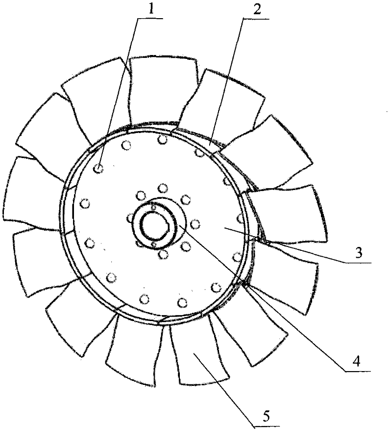
[0017] This embodiment includes a blade disc 2 , a spoke disc 3 , a hub 4 , a blade 5 and a petiole 8 .

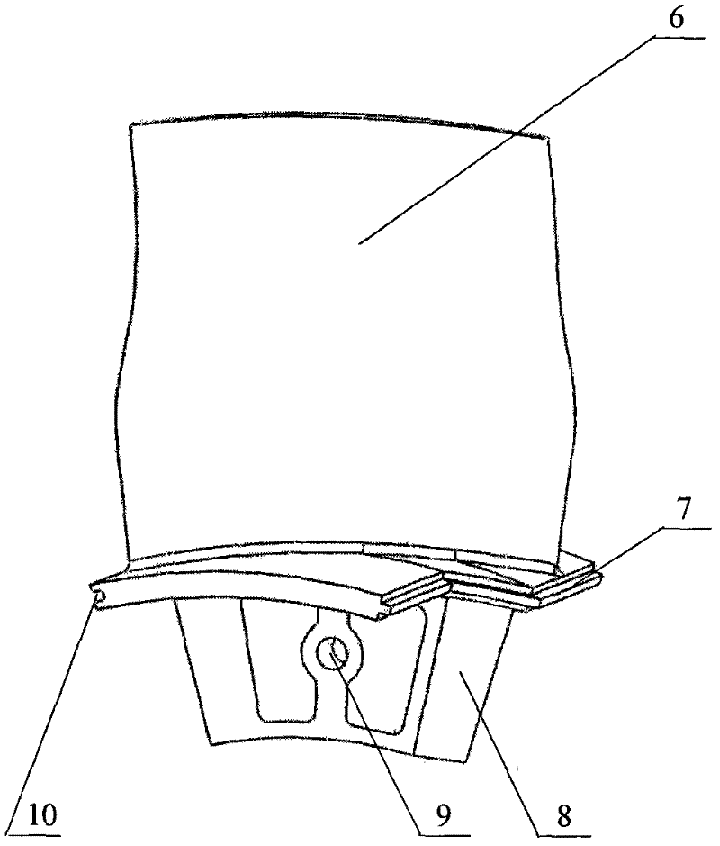
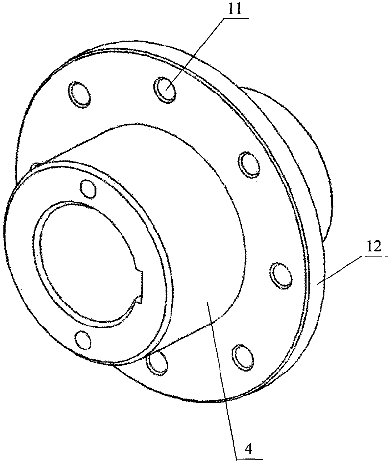
[0018] The blade flap 6 is composed of the blade 5, the tenon 7, the petiole 8, the connecting hole 9 and the tenon and groove 10, and is integrally cast with aluminum alloy. There is a radially protruding petiole mounting plate 12 in the middle of the hub 4 ; the blade 5 is fixed on the petiole mounting plate 12 of the hub 4 through the petiole 8 . The two spoke discs 3 are set on the two ends of the petiole mounting disc 12 on the hub 4 and fixed by bolts 1 . The blade wheel disc 2 is sleeved on the hub 4 . The blade wheel 2 is formed by splicing 13 blade wheel petals 6 . There are tenons 7 and tenon grooves 10 on both sides of the blade wheel disc 6, and the tenon 7 on each blade wheel disc 6 is embedded in the tenon 10 on the other adjacent blade wheel disc 6. Inside, a complete cylindrical blade wheel disc 2 ...

Embodiment 2

[0022] This embodiment is an axial flow fan impeller.

[0023] This embodiment includes a blade disc 2 , a spoke disc 3 , a hub 4 , a blade 5 and a petiole 8 .

[0024] The blade flap 6 is composed of the blade 5, the tenon 7, the petiole 8, the connecting hole 9 and the tenon and groove 10, and is integrally cast by engineering plastic nylon. There is a radially protruding petiole mounting plate 12 in the middle of the hub 4 ; the blade 5 is fixed on the petiole mounting plate 12 of the hub 4 through the petiole 8 . The two spoke discs 3 are set on the two ends of the petiole mounting disc 12 on the hub 4 and fixed by bolts 1 . The blade wheel disc 2 is sleeved on the hub 4 . The blade wheel disc 2 is formed by splicing 18 blade wheel disc petals 6 . There are tenons 7 and tenon grooves 10 on both sides of the blade wheel disc 6, and the tenon 7 on each blade wheel disc 6 is embedded in the tenon 10 on the other adjacent blade wheel disc 6. Inside, a complete cylindrical ...

Embodiment 3

[0028] This embodiment is an axial flow fan impeller.

[0029] This embodiment includes a blade disc 2 , a spoke disc 3 , a hub 4 , a blade 5 and a petiole 8 .

[0030] The blade flap 6 is composed of the blade 5, the tenon 7, the petiole 8, the connecting hole 9 and the tenon and groove 10, and is integrally cast by engineering plastic MPPO. There is a radially protruding petiole mounting plate 12 in the middle of the hub 4 ; the blade 5 is fixed on the petiole mounting plate 12 of the hub 4 through the petiole 8 . The two spoke discs 3 are set on the two ends of the petiole mounting disc 12 on the hub 4 and fixed by bolts 1 . The blade wheel disc 2 is sleeved on the hub 4 . The blade wheel disc 2 is formed by splicing 20 blade wheel disc petals 6 . There are tenons 7 and tenon grooves 10 on both sides of the blade wheel disc 6, and the tenon 7 on each blade wheel disc 6 is embedded in the tenon 10 on the other adjacent blade wheel disc 6. Inside, a complete cylindrical b...


PUM


Abstract

The invention relates to an axial flow fan propeller, wherein an blade-disk sleeved on a hub is spliced by a plurality of blade-disk petals; the both sides of each blade-disk petal are separately provided with a tenon and a mortise; and the tenon of each blade-disk petal is embedded in the mortise of another adjacent blade-disk petal, and the blade-disk petals are sleeved and spliced to form the complete blade-disk. The center of each blade handle is provided with a connecting hole; and mounting holes for the blade handles are uniformly distributed on a blade handle mounting disk, and the positions of the mounting holes correspond to those of the connecting holes of the blade handles. Hub connecting holes are uniformly distributed on the edge of the excircle of a spoke disk and used for connecting the spoke disk with a connecting hub 4, and blade handle connecting holes are uniformly distributed on the edge of the incircle of the spoke disk and used for connecting the spoke disk with the blade handles. By adopting the invention, the uniformity of the machining precision and strength of the blade-disk can be increased, the machining cost can be reduced, the reliability and the machining precision can be increased; and the fan blade can be changed conveniently in situ, and the service life of the fan can be prolonged.

Description

technical field [0001] The invention relates to the fan field, and relates to an axial flow fan impeller. Background technique [0002] Fans are ventilation equipment. Axial flow fans are an important and large-scale fan. Axial flow fans are widely used in coal mines, mines, tunnels, chemical, energy, and textile industries to play their role in ventilation and dust removal. [0003] The performance of the axial flow fan is closely related to the performance of the fan impeller. The fan impeller is generally composed of a group of blades, blade discs, hubs, spoke discs and other components, and its core components are blades and blade discs. For the processing of the core components of the fan impeller, there are two methods in the prior art, one is the split processing method, and the other is the integral processing method. [0004] The split processing method is to process the blades and blade discs of each monomer separately first, and then weld the blades of each mono...

Claims


Application Information

Patent Timeline
IPC IPC(8): F04D29/32
Inventor 苏莫明李世武郭建民郝凡森
Owner NORTHWESTERN POLYTECHNICAL UNIV
Learn More