
Novel kinetic energy recovery type wind drum of novel cooling tower fan

A kinetic energy recovery, cooling tower technology, used in water shower coolers, heat exchanger types, direct contact heat exchangers, etc., can solve the problems of airflow separation and high cost, achieve forced airflow contraction, and reduce manufacturing costs. The effect of resistance

Inactive Publication Date: 2011-04-20
CHINA NAT ENERGY REFINING & CHEM ENG CO LTD
View PDF4 Cites 0 Cited by
  • Summary
  • Abstract
  • Description
  • Claims
  • Application Information

AI Technical Summary

Problems solved by technology

Such an air duct is not only costly, but also prone to separation of airflow

Method used


Image

  • Novel kinetic energy recovery type wind drum of novel cooling tower fan
  • Novel kinetic energy recovery type wind drum of novel cooling tower fan
  • Novel kinetic energy recovery type wind drum of novel cooling tower fan

Examples


Embodiment Construction

[0020] The present invention relates to a novel cooling tower air duct, the following measures are adopted in the design:

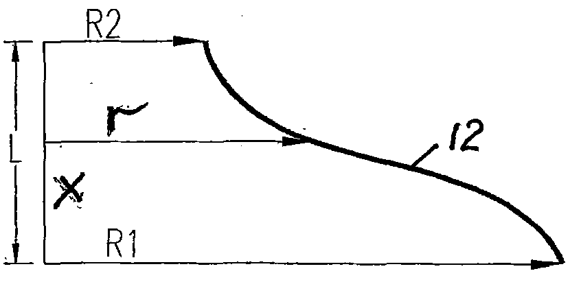
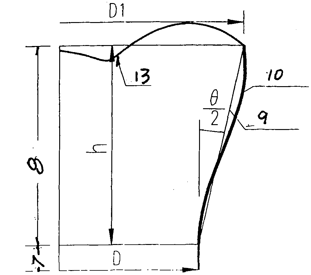
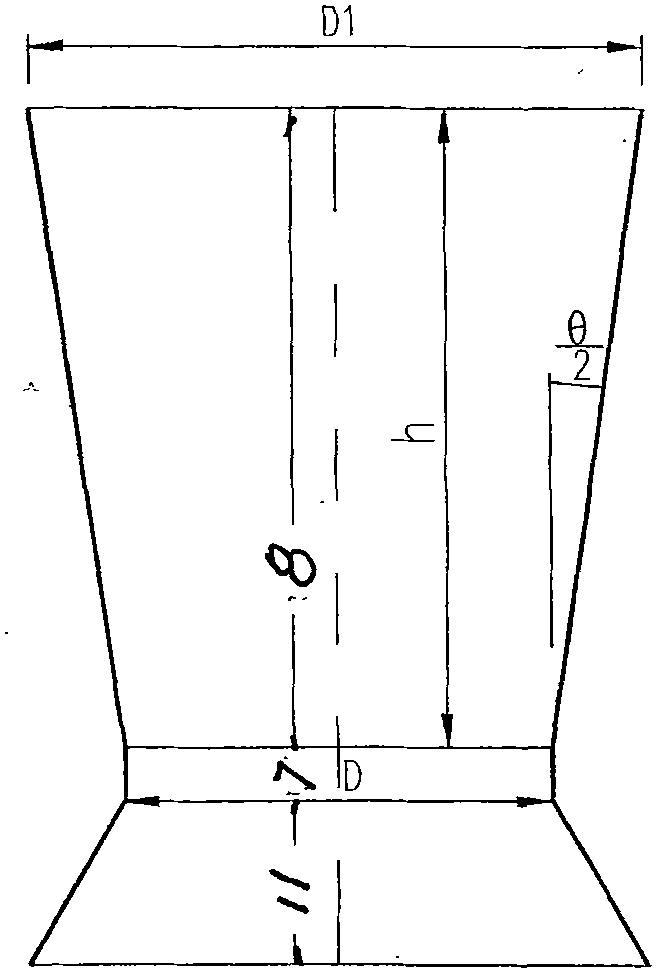
[0021] (1) The airflow contraction section below the throat of the air duct adopts the Witoshinski curve that is suitable for the contraction ratio of this part, see the attached Figure 4 Medium 1 method one;

[0022] (2) The diffuser above the throat of the air duct is divided into two sections according to height. The first section is a section with a height-to-diameter ratio (h / D) between 0 and 0.3, and the maximum diffusion angle is 29°. See attached Figure 4 Secondary 2 method two;

[0023] (3) The second section is from the height-to-diameter ratio (h / D) of 0.3 to the outlet section of the air duct. The curve of the diffuser is closed to avoid the separation of the air flow from the wall of the air duct and the vortex, and it can also reduce the vortex in the central area of ​​the air duct. Negative pressure zone, see appendix Figure 4 Method ...


PUM


Abstract

The invention relates to a kinetic energy recovery type wind drum of a novel cooling tower fan. In the invention, a hatching line of the vertical side wall of the wind drum has a shape that an airflow contraction section below a middle lower throat part adopts a Witoszynski curve with a contraction ratio appropriate to the contraction ratio of the airflow contraction section; a diffusion drum above the throat part is divided into two sections according to the height, wherein the height-to-diameter ratio of the first section is 0-0.3, the maximum diffusion angle is 29 degrees, the height-to-diameter ratio of the second section is larger than 0.3 to an outlet section, and the curve of the diffusion drum is tucked up; an upper outlet of the diffusion drum is formed in a curve form after tucking up, and a last section is close to a vertical section; and the throat part is a vertical segment. The wind drum can be used for effectively forcing airflows to contract and reduce the contraction resistance of the airflows; and airflows at the outlet of a fan are reasonably diffused according to the flow state natural instincts and constrained to be exhausted into atmosphere, which can reduce the height of the wind drum, reduce the thickness of the wall of the wind drum, avoid the airflows from separating, shorten a central negative pressure area above a hub and recover partial kinetic energy. The invention can reduce the wind bearing load of the wind drum, improve the stability, prolong the service life, reduce the cost by 50 percent and reduce the negative pressure area, and the kinetic energy recovery rate reaches 26-30 percent.

Description

technical field [0001] The patent of the invention belongs to cooling tower components, and in particular relates to a new cooling tower fan kinetic energy recovery type air duct. Background technique [0002] The energy of the cooling tower fan is mainly used to overcome the resistance generated by the airflow in the cooling tower, and to The remaining energy diffuses into the atmosphere, and the airflow passes through the throat of the fan at the highest velocity. If the air is discharged into the atmosphere at such a velocity, the kinetic energy provided by the fan is the largest, and the energy loss is the highest. After adding the diffuser, the air outlet area is expanded from the throat area to the outlet area, the flow velocity is reduced, and the residual energy lost is also reduced. The diffusion tubes of the early air ducts were all inverted truncated cones, which looked like an oblique straight line from the cross section. The central diffusion angle was general...

Claims


Application Information

Patent Timeline
Patent Type & Authority Applications(China)
IPC IPC(8): F28F25/10
Inventor 胡连江王敬
Owner CHINA NAT ENERGY REFINING & CHEM ENG CO LTD
Learn More