
Current detecting method, inverter device and convertor device using the same

A technology of current detection and current detection unit, which is applied in the field of inverter devices and converter devices, can solve the problems of large AC current reproduction error and instability, and achieve the goals of reducing distortion, stabilizing motor control, and expanding the output range Effect

Active Publication Date: 2011-04-20
HITACHI JOHNSON CONTROLS AIR CONDITIONING INC
View PDF5 Cites 15 Cited by
  • Summary
  • Abstract
  • Description
  • Claims
  • Application Information

AI Technical Summary

Problems solved by technology

[0004] However, as will be described in detail below, in general, in the above-mentioned overmodulation region, a phenomenon occurs in which only the current of one of the plurality of phases (for example, three phases) can be detected by the above-mentioned current detection means within a certain period of time.
In addition, when this phenomenon occurs, the reproduction error in the alternating current generated by the inverter device increases, and the control by the motor drive device may become unstable, making it difficult to actually implement the above-mentioned overmodulation control.

Method used


Image

  • Current detecting method, inverter device and convertor device using the same
  • Current detecting method, inverter device and convertor device using the same
  • Current detecting method, inverter device and convertor device using the same

Examples


Embodiment Construction

[0032]Hereinafter, embodiments of the present invention will be described in detail with reference to the drawings. The current detection method of the present invention will be described in detail in the description of the motor drive device using the method described in detail below.

[0033] (motor drive unit)

[0034] (Structure of the device)

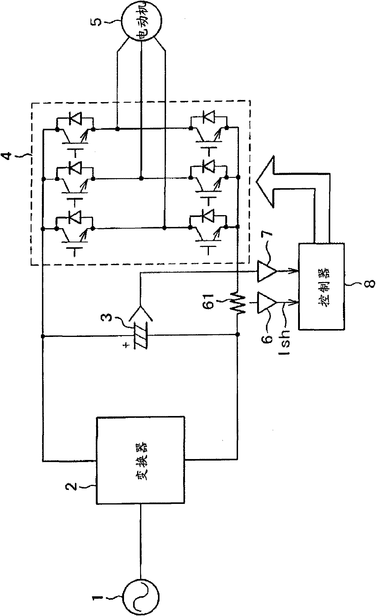
[0035] figure 1 It is a configuration diagram of a motor drive device for a three-phase motor according to an embodiment of the present invention. As can be seen from this figure, the motor drive device includes: an inverter (rectifier, etc.) 2 for converting AC to DC, a DC capacitor 3, The inverter 4 that converts DC to AC, the current detection unit 6 that detects the bus current on the DC side of the inverter, the voltage detection unit 7 that detects the DC voltage, and the controller 8 receive power from the AC power supply 1 to drive the AC Motor 5. It can also be seen from the drawings that the current detection unit 6 f...


PUM


Abstract

The invention provides a current detecting method capable of stably operating even in an over-modulation area, an inverter device and a convertor device using the same. In a motor driving device having an alternated current motor, a current detecting unit for detecting the bus bar current or each branch current at the direct current side of the inverter and the convertor for driving the alternated current motor, and a control unit for controlling the alternated current motor by using a current detected value acquired from detection, a current reference value of the alternated current motor is calculated by using a past detected value of the current acquired from the current detecting unit or a current instruction value of the control unit, the error between a one phase current detected value and the current reference value is calculated when only the one phase current of the alternated current motor can be detected by the current detecting unit, and the current at other phases of the alternated current motor can be presumed by using the error.

Description

technical field [0001] The present invention relates to a current detection method, in particular to a current detection method suitable for detecting the current in a conversion device such as an inverter device that converts direct current to alternating current or a converter device that converts alternating current to direct current, and also relates to the use of the current detection method The method provides an inverter device and a converter device, and relates to a motor drive device and a refrigerating and air-conditioning device equipped with the device. Hereinafter, the inverter device and the converter device are collectively referred to as "conversion device". Background technique [0002] In the fields of industrial equipment and home appliances, an inverter device for driving a motor that converts direct current to three-phase alternating current or an inverter device that converts three-phase alternating current to direct current is widely used. In particu...

Claims


Application Information

Patent Timeline
IPC IPC(8): G01R19/00H02P27/06H02M7/48H02M7/02H02P29/00H02P21/00H02P21/14H02P21/18H02P21/22H02P21/24H02P23/00H02P23/07H02P23/14H02P27/08
CPCH02P6/18H02P27/06H02P27/14H02P29/02
Inventor 李东升能登原保夫
Owner HITACHI JOHNSON CONTROLS AIR CONDITIONING INC
Learn More