Clamp-type surgical instrument for abdominal cavity minimally invasive surgery robot
A technology of minimally invasive surgery and surgical instruments, which is applied in surgical forceps, surgical robots, surgery, etc., can solve the problems of uncompensated left and right finger movements, easy to break steel wires, etc., and achieves high flexibility and easy operation. Easy, large workspace effect
- Summary
- Abstract
- Description
- Claims
- Application Information
AI Technical Summary
Problems solved by technology
Method used
Image

Examples
specific Embodiment approach 1
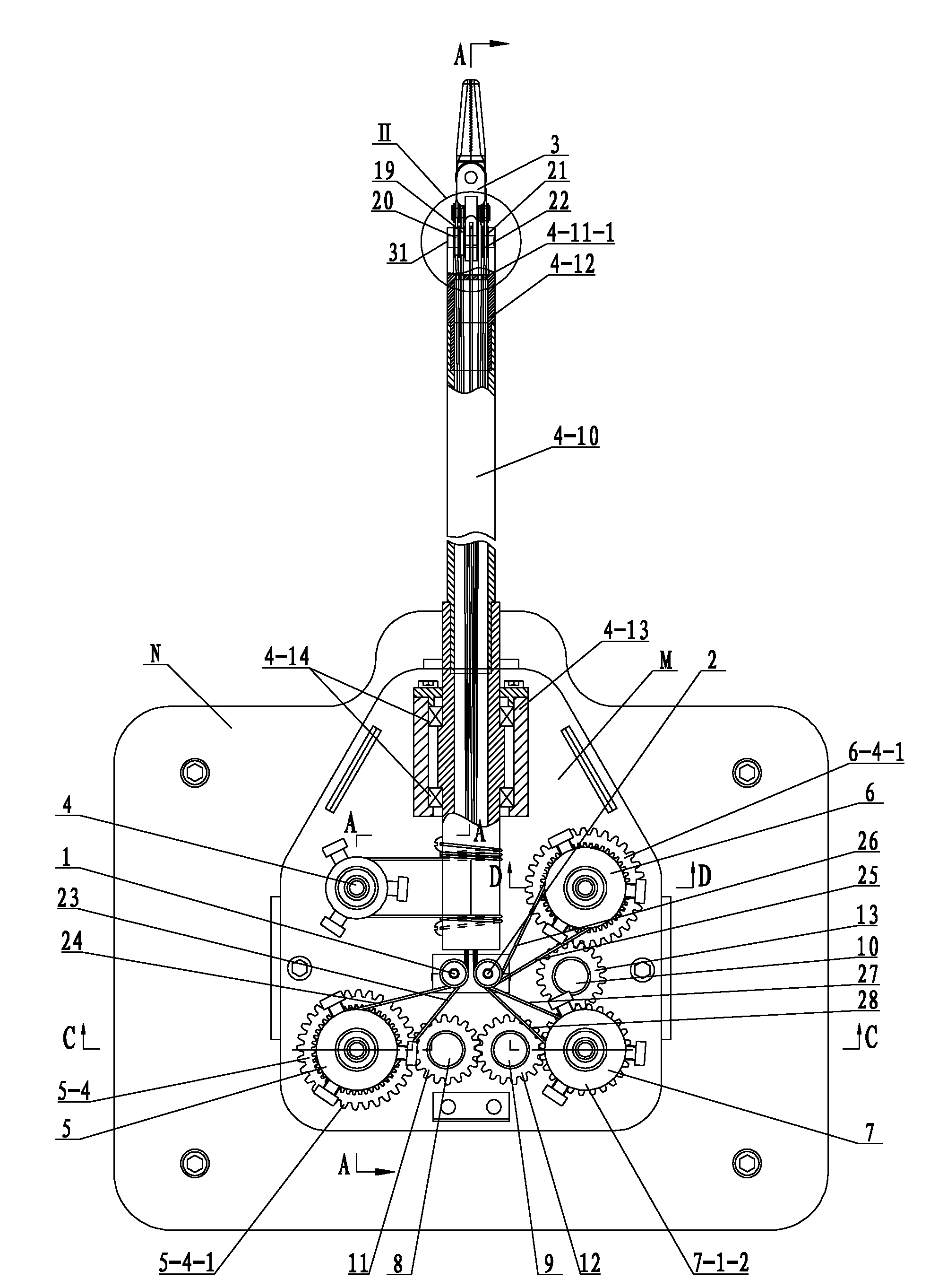
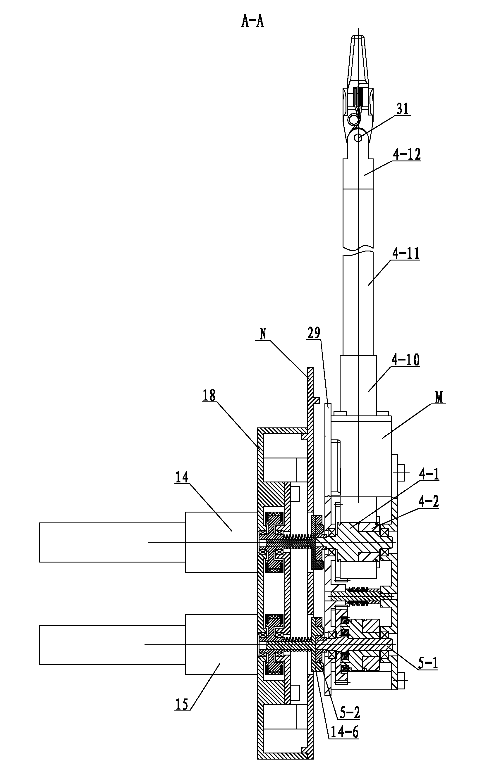
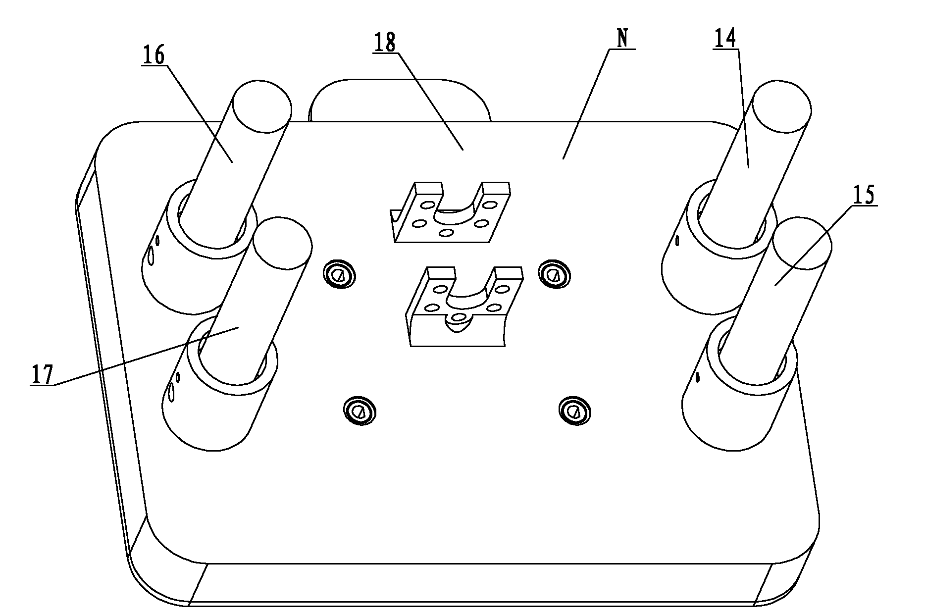
[0007] Specific implementation mode one: combine Figure 1 to Figure 15 , Figure 18 , Figure 19 , Figure 25 and Figure 26This embodiment is described. This embodiment includes a surgical instrument M and an interface base N. The interface base N is composed of an operation tube drive mechanism 14, a left finger drive mechanism 15, a right finger drive mechanism 16, a wrist joint drive mechanism 17 and a base housing. 18, the front end of the base housing 18 is provided with a first mounting hole 18-1, a second mounting hole 18-2, a third mounting hole 18-3 and a fourth mounting hole 18-4, the first mounting hole 18 -1 and the third installation hole 18-3 are arranged symmetrically with the vertical centerline of the base shell 18, and the second installation hole 18-2 and the fourth installation hole 18-4 are arranged symmetrically with the vertical centerline of the base casing 18 , and the second mounting hole 18-2 is located below the first mounting hole 18-1, the f...
specific Embodiment approach 2
[0008] Specific implementation mode two: combination figure 2 and Figure 7 , figure 1 and figure 2Describe this embodiment, the operating tube driving mechanism 14, the left finger driving mechanism 15, the right finger driving mechanism 16 and the wrist joint driving mechanism 17 of this embodiment are all composed of a motor 14-1, a connecting piece 14-2, a driving pulley 14- 3. Synchronous belt 14-4, driven pulley 14-5, interface clutch disc 14-6 and spring 14-7, interface clutch disc 14-6 is made of an integrated disc 14-6-1 from front to back Composed with the driven pulley shaft 14-6-2, the front end of the disc 14-6-1 is provided with two interface protrusions 14-6-3, the spring 14-7 and the driven pulley 14-5 are from inside to outside Installed on the driven pulley shaft 14-6-2, the driven pulley 14-5 is connected with the driving pulley 14-3 through the timing belt 14-4, and the driving pulley 14-3 is installed on the output end of the connector 14-2 , the inp...
specific Embodiment approach 3
[0009] Specific implementation mode three: combination figure 1 , Figure 11 , Figure 12 and Figure 13 Describe this embodiment, the operating tube transmission mechanism 4 of this embodiment is composed of a transmission rear wire wheel shaft 4-1, a transmission front wire wheel 4-2, a transmission front bearing 4-3, a transmission rear bearing 4-4, an operation tube clutch disc 4- 5. Steel wire after traction 4-6, steel wire before traction 4-7, first screw 4-8, second screw 4-9, casing 4-10, operating tube 4-11, wrist joint connector 4-12, Bearing seat 4-13, two bushing bearings 4-14 and three operating pipe jacking wires 4-15 are formed, and the wire wheel shaft 4-1 after transmission is successively made into one section of wire wheel shaft 4-1- 1. The second section of the spool shaft is 4-1-2, the third section of the spool shaft is 4-1-3, the fourth section of the spool shaft is 4-1-4, and the fifth section of the spool shaft is 4-1-5, and the third section of the...
PUM
 Abstract
Description
Claims
Application Information
 - R&D
- Intellectual Property
- Life Sciences
- Materials
- Tech Scout
- Unparalleled Data Quality
- Higher Quality Content
- 60% Fewer Hallucinations
Browse by: Latest US Patents, China's latest patents, Technical Efficacy Thesaurus, Application Domain, Technology Topic, Popular Technical Reports.
© 2025 PatSnap. All rights reserved.Legal|Privacy policy|Modern Slavery Act Transparency Statement|Sitemap|About US| Contact US: help@patsnap.com