
Clamp-type surgical instrument for abdominal cavity minimally invasive surgery robot

A technology of minimally invasive surgery and surgical instruments, applied in surgical forceps, surgical robots, surgery, etc., can solve the problems of easy breaking of steel wires, uncompensated left and right finger redundant movements, etc., to achieve easy operation and flexibility High, high stiffness effect

Active Publication Date: 2012-03-07
杭州唯精医疗机器人有限公司
View PDF1 Cites 4 Cited by
  • Summary
  • Abstract
  • Description
  • Claims
  • Application Information

AI Technical Summary

Problems solved by technology

[0003] The purpose of the present invention is to solve the problem that the existing clamp-type surgical instrument for minimally invasive surgery robot uses a motor to drive the wire wheel and then drive the steel wire to realize the rotation of the operation tube, wrist joint, left finger and right finger. When the wrist joint rotates, the left finger The excess movement of the left and right fingers cannot be compensated, resulting in the problem that the steel wires driving the left and right fingers are easily broken, and a clamp-type surgical instrument for a minimally invasive abdominal surgery robot is provided

Method used


Image

  • Clamp-type surgical instrument for abdominal cavity minimally invasive surgery robot
  • Clamp-type surgical instrument for abdominal cavity minimally invasive surgery robot
  • Clamp-type surgical instrument for abdominal cavity minimally invasive surgery robot

Examples


specific Embodiment approach 1

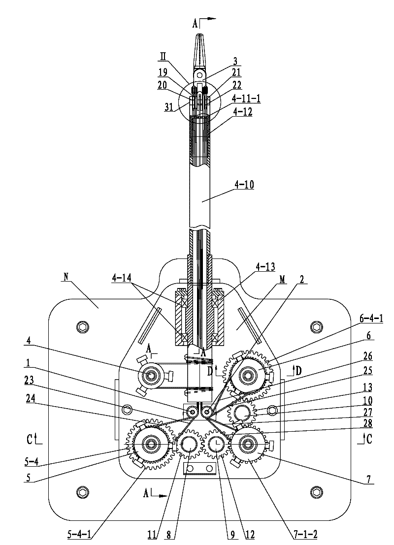
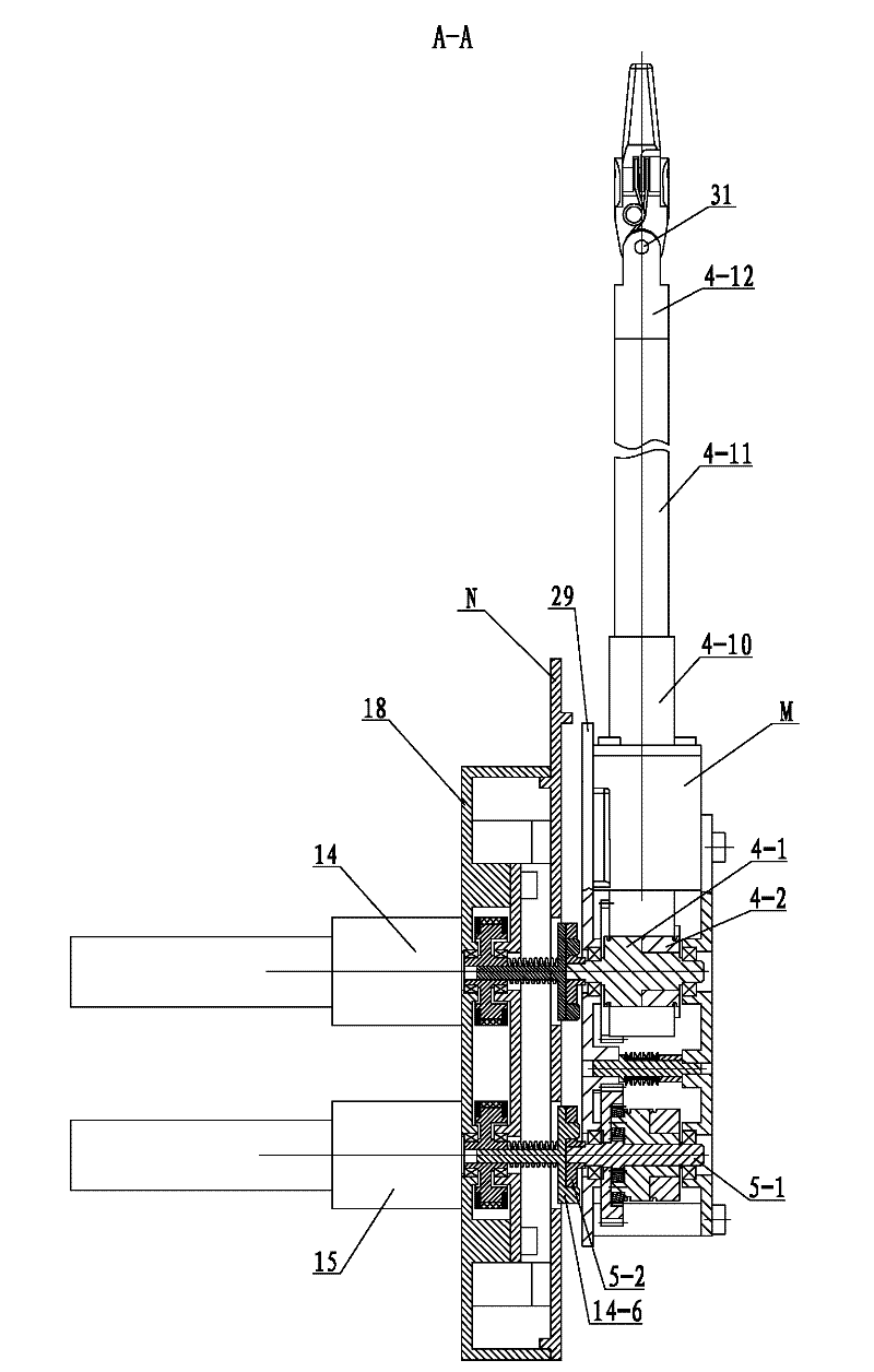
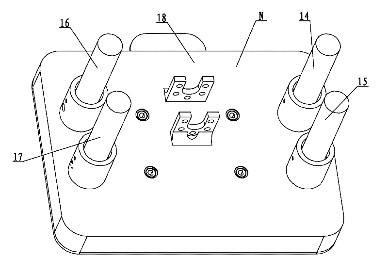
[0007] Specific implementation mode one: combine Figure 1 to Figure 15 , Figure 18 , Figure 19 , Figure 25 with Figure 26Describe this embodiment. This embodiment includes a surgical instrument actuator M and an interface base N. The housing 18 is composed of a first mounting hole 18-1, a second mounting hole 18-2, a third mounting hole 18-3 and a fourth mounting hole 18-4 on the front face of the base housing 18. The hole 18-1 and the third installation hole 18-3 are arranged symmetrically with the vertical center line of the base housing 18, and the second installation hole 18-2 and the fourth installation hole 18-4 are arranged with the vertical center line of the base housing 18. Symmetrically arranged, and the second installation hole 18-2 is located below the first installation hole 18-1, the fourth installation hole 18-4 is located below the third installation hole 18-3, and the rear end surface of the base shell 18 is provided with The fifth mounting hole 18-...

specific Embodiment approach 2

[0008] Specific implementation mode two: combination figure 2 with Figure 7 , figure 1 with figure 2Describe this embodiment, the operating tube driving mechanism 14, the left finger driving mechanism 15, the right finger driving mechanism 16 and the wrist joint driving mechanism 17 of this embodiment are all composed of a motor 14-1, a connecting piece 14-2, a driving pulley 14- 3. Synchronous belt 14-4, driven pulley 14-5, interface clutch disc 14-6 and spring 14-7, interface clutch disc 14-6 is made of an integrated disc 14-6-1 from front to back Composed with the driven pulley shaft 14-6-2, the front end of the disc 14-6-1 is provided with two interface protrusions 14-6-3, the spring 14-7 and the driven pulley 14-5 are from inside to outside Installed on the driven pulley shaft 14-6-2, the driven pulley 14-5 is connected with the driving pulley 14-3 through the timing belt 14-4, and the driving pulley 14-3 is installed on the output end of the connector 14-2 , the i...

specific Embodiment approach 3

[0009] Specific implementation mode three: combination figure 1 , Figure 11 , Figure 12 with Figure 13 Describe this embodiment, the operating tube transmission mechanism 4 of this embodiment is composed of a transmission rear wire wheel shaft 4-1, a transmission front wire wheel 4-2, a transmission front bearing 4-3, a transmission rear bearing 4-4, an operation tube clutch disc 4- 5. Steel wire after traction 4-6, steel wire before traction 4-7, first screw 4-8, second screw 4-9, casing 4-10, operating tube 4-11, wrist joint connector 4-12, Bearing seat 4-13, two bushing bearings 4-14 and three operating pipe jacking wires 4-15 are formed, and the wire wheel shaft 4-1 after transmission is successively made into one section of wire wheel shaft 4-1- 1. The second section of the spool shaft is 4-1-2, the third section of the spool shaft is 4-1-3, the fourth section of the spool shaft is 4-1-4, and the fifth section of the spool shaft is 4-1-5, and the third section of th...


PUM


Abstract

The invention discloses a clamp-type surgical instrument for an abdominal cavity minimally invasive surgery robot, relates to the clamp-type surgical instrument for the abdominal cavity minimally invasive surgery robot and aims to solve the problem of easy tensile failure of a steel wire which drives left fingers and right fingers due to failed compensation of residual movement of the left fingers and the right fingers during rotating of wrist joints because the steel wire is driven to rotate an operating pipe, the wrist joints, the left fingers and the right fingers by a motor driving wire wheel in the clamp-type surgical instrument for the conventional abdominal cavity minimally invasive surgery robot. The surgical instrument actuating mechanism is connected with an interface base and drives an operating pipe transmission mechanism, a left finger transmission mechanism, a right finger transmission mechanism and a wrist joint transmission mechanism on the surgical instrument actuating mechanism respectively through four driving mechanisms on the interface base; and the wrist joints, the left fingers and the right fingers on a tail end actuating mechanism are driven to move by a left finger front driving steel wire, a left finger back driving steel wire, a right finger front driving steel wire, a right finger back driving steel wire, a wrist joint front driving steel wire and a wrist joint back driving steel wire. The clamp-type surgical instrument is applied to abdominal cavity minimally invasive surgery.

Description

technical field [0001] The invention relates to a clamp-type surgical instrument for a minimally invasive abdominal surgery robot. Background technique [0002] Minimally invasive surgery refers to the operation performed on the human body through a minimum small incision. It is also generally called interventional surgery. Robot-assisted minimally invasive surgery uses various visual image equipment and advanced and dexterous surgical instruments to enter the human body through a small incision. The human body for treatment or diagnosis. The patent application number is 200910073301.6, the publication number is CN 101732093A, and the publication date is June 16, 2010. The invention patent application discloses a "clamp type surgical instrument for minimally invasive abdominal surgery robot", which is driven by a motor The wire wheel then drives the steel wire to realize the rotation of the operation tube, wrist joint, left finger and right finger. Although this patent incr...

Claims


Application Information

Patent Timeline
Patent Type & Authority Patents(China)
IPC IPC(8): A61B19/00A61B17/29A61B34/30
Inventor 王树国冯美曹校铭潘博刘昶付宜利
Owner 杭州唯精医疗机器人有限公司
Learn More