Multi-stage perforation supercharging method

A technology of perforating and perforating gun, applied in the field of TCP tubing transmission perforation in oil and gas wells, can solve the problems of reliability, poor safety, high working intensity, low reliability, etc. Guaranteed effect of stability

Active Publication Date: 2011-04-27
CHUANNAN ENERGY TECH CO LTD
View PDF8 Cites 24 Cited by
  • Summary
  • Abstract
  • Description
  • Claims
  • Application Information

AI Technical Summary

Problems solved by technology

[0004] The main problems in the perforating process with interlayer guns are: for perforating with large intervals and multi-layer sections, there are many interlayer guns, the workload is large, the operation intensity is high, the cost is high, and there are many explosion transmission links and low reliability.
The main problems in the staged perforation process with multiple pressure ignition heads are: the casing needs to be pressurized for perforation, and when re-perforating an old well that has been perforated, the formation communicates with the casing, and it is impossible to pressurize for negative pressure perforation. And the well killing fluid enters the formation during pressurization, which may contaminate the formation
The main problems in the multi-stage rod-casting perforating process are: the rod-dropping operation relies on gravity impact to detonate the next-stage perforating gun, which is not suitable for perforating operations in highly inclined wells and horizontal wells; , in order to avoid false perforation, the string must be pulled up before the rod can be lifted, but the multi-stage rod throwing detonation device cannot carry out the rod fishing operation; the multi-stage throwing rod perforating process has a self-destruct device for the rods above the second level, but During construction, the self-destruct device still has the risk of not detonating, and the engineering accident treatment takes a long time, and the reliability and safety are poor

Method used


Image

  • Multi-stage perforation supercharging method
  • Multi-stage perforation supercharging method
  • Multi-stage perforation supercharging method

Examples


Embodiment Construction

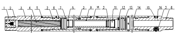
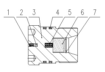
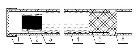
[0035]A multi-stage perforation boosting method, including the following process: a multi-stage perforation booster device is connected to the tail of the upper-stage perforating gun, and after the upper-stage perforating gun is detonated, the perforating gun sends the detonation wave Transfer to the supercharging device, detonate the diaphragm igniter of the supercharging device, the diaphragm igniter ignites the supercharged powder mechanism, and the supercharged propellant mechanism generates high-pressure gas to drive the supercharged piston to move, cut the copper shear pin, and push the piston to squeeze the interlayer The liquid in the oil pipe increases the pressure in the interlayer oil pipe, cuts off the shear pin of the next-stage pressure detonator, detonates the next-stage pressure detonator and perforating gun, and completes the perforation operation of the next layer. The pressure detonation device in the present invention can adopt the pressure detonation device...


PUM


Abstract

The invention discloses a multi-stage perforation supercharging method. In the technological processes, a supercharging device is connected with the tail of a perforation gun of the upper level, after the perforation gun of the upper level is detonated, the perforation gun transmits detonation waves to the supercharging device, a baffle igniter of the supercharging device is detonated to ignite a supercharging gun powder mechanism, the supercharging gun powder mechanism generates high-pressure gas to push a supercharging piston to move to shear a shear pin of the supercharging device, and to push the piston to extrude a liquid inside an interlayer oil pipe so as to increase the pressure inside the interlayer oil pipe, and the shear pin of the lower-level detonation device is shorn off to detonate a pressure detonation device and a perforation gun of the lower level so as to complete the perforation operation of the lower level. The method can ensure the stability and the controllability of pressure generated due to the combustion of supercharging gun powder in a supercharging cavity, the pressure is then acted on the supercharging piston to ensure that the supercharging piston moves stably, the method can also realize high-precision shearing, can be used in a pressure type multi-stage perforation process, and is suitable for various well conditions.

Description

technical field [0001] The invention relates to the field of TCP tubing transmission perforation for oil and gas wells, in particular to a TCP multistage perforation pressurization method. Background technique [0002] In the petroleum industry, oil well perforation operation is an important process, which is to lower the perforating gun into the target layer in the well, use the detonating device to detonate, and after detonation, the shaped charge will penetrate the perforating gun, casing and cement layer. The exit channel connects the stratum with the oil well, so that the formation oil and gas can flow into the oil well smoothly. [0003] Multi-stage perforation technology refers to the perforation technology that penetrates multiple oil and gas layers at one time in the case of the next pipe string, which can reduce the number of perforations and save operating time and cost. The conventional multi-stage perforation operation methods are the perforation process with i...

Claims


Application Information

Patent Timeline
Patent Type & Authority Applications(China)
IPC IPC(8): E21B43/117E21B43/1185E21B43/119
Inventor 重成兴唐其林徐德昭
Owner CHUANNAN ENERGY TECH CO LTD
Why Eureka
Try Eureka