Valve opening/closing timing control device
A timing control and valve technology, applied in valve device, engine control, machine/engine, etc., can solve the problems of complex and large valve opening/closing timing control device, and achieve the effect of mechanical simplicity
- Summary
- Abstract
- Description
- Claims
- Application Information
AI Technical Summary
Problems solved by technology
Method used
Image

Examples
no. 1 approach
[0046] (basic structure)
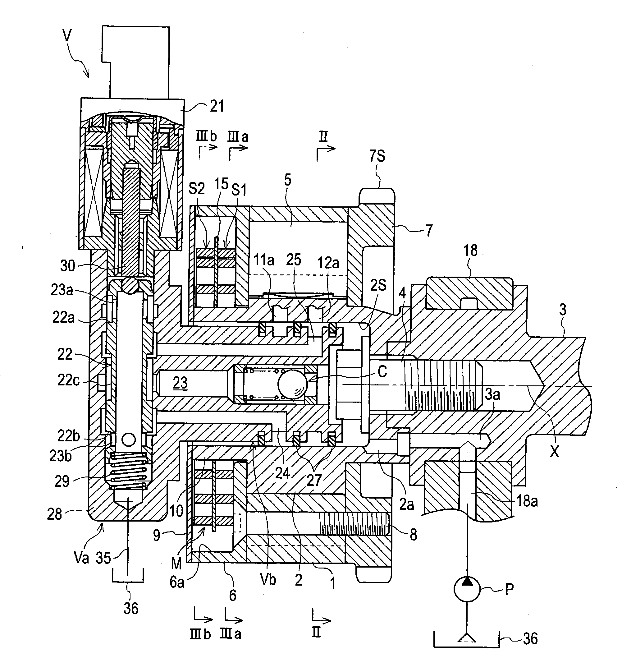
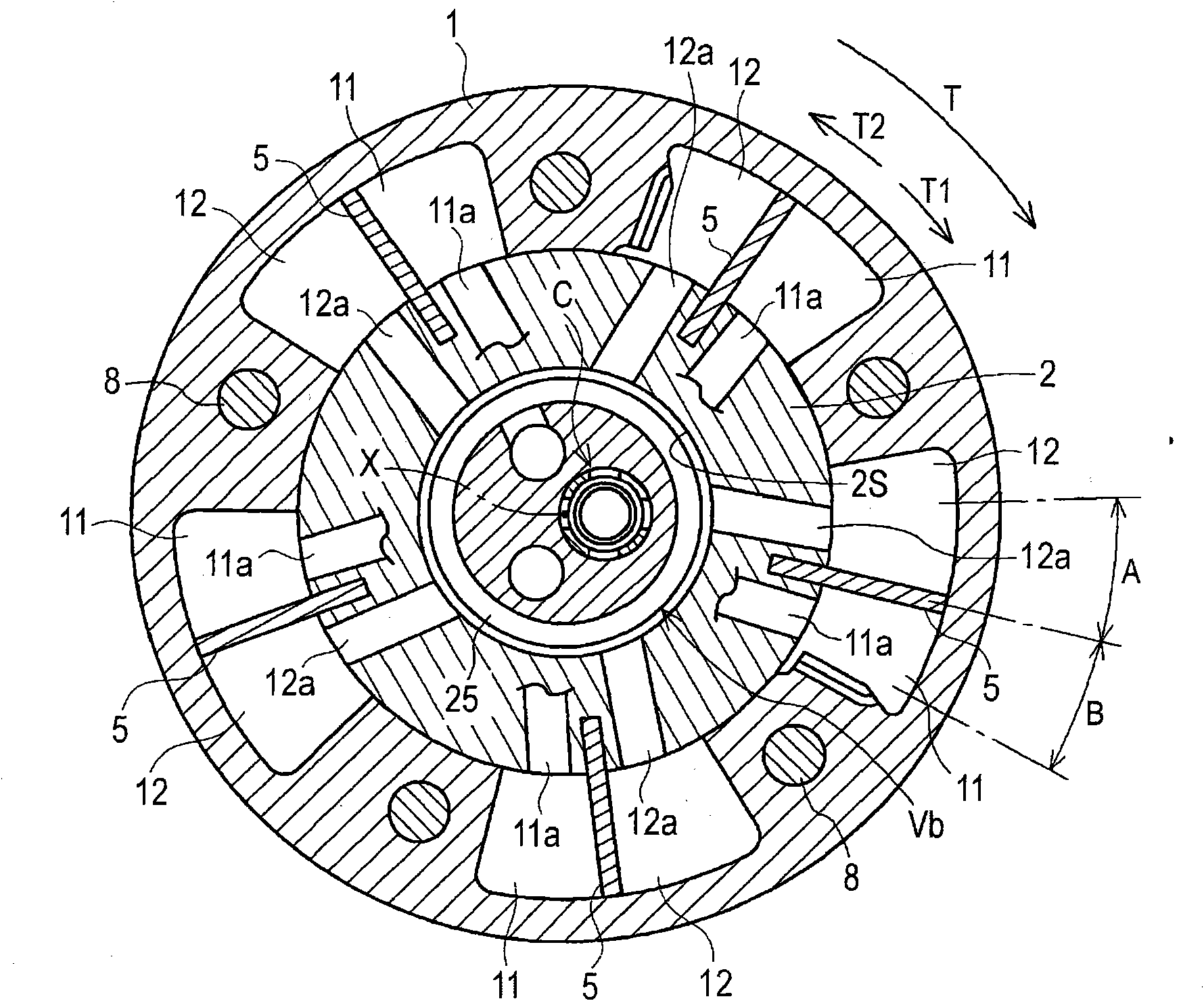
[0047] Such as figure 1 As shown, the valve opening / closing timing control device includes an outer rotor 1 serving as a driving side rotating member and capable of rotating synchronously with a crankshaft (not shown) of an engine (internal combustion engine), serving as a driven side rotating member and capable of rotating with The inner rotor 2 is coaxial and rotates synchronously with the camshaft 3, which opens and closes the intake or exhaust valves in the combustion chamber of the engine, and the fluid control valve train V.
[0048] The valve opening / closing timing control device includes a structure in which an inner rotor 2 (a driven-side rotating member) is inserted into an outer rotor 1 (a driving-side rotating member). Therefore, the outer rotor 1 and the inner rotor 2 can relatively rotate around the rotation axis X within a range of a desired relative rotational phase. A fluid pressure chamber is formed between the outer rotor 1 and t...
no. 2 approach
[0096] A second embodiment disclosed herein will be described below with reference to the drawings.
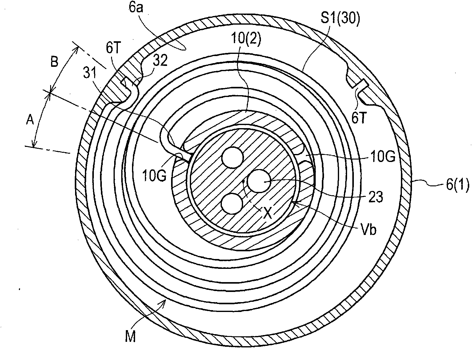
[0097] Similar to the first embodiment, the second embodiment includes two coil springs S1 and S2 as a holding mechanism M for holding the relative rotational phase of the outer rotor 1 and the inner rotor 2 at the optimum phase for starting. Springs S1 and S2 apply biasing forces in opposite directions to each other, and the starting optimum phase is suitable for engine starting.
[0098] Such as Figures 9A to 12 As shown, the first feature of the structure according to the second embodiment is that the width of the engagement recessed portion 10G of the inner rotor 2 in the circumferential direction is sufficiently larger than the thickness of the inner engagement portion 31 of the coil springs S1 and S2. With the above structure, the respective inner engaging portions 31 engaged to the engaging recessed portion 10G are movable in the circumferential direction in the engag...
no. 3 approach
[0105] Instead of a coil spring, the third embodiment uses two torsion springs S1 and S2 as biasing members for maintaining the relative phase at the optimum phase for starting, as Figure 13 and Figure 14A and 14B shown. A first torsion spring S1 biasing the relative phase toward the advanced angle side is accommodated in the recessed portion 6 a of the front plate 6 , and a second torsion spring S2 biasing the relative phase toward the retarded angle side is accommodated in the recessed portion of the rear plate 7 7a.
[0106] Figure 14A and 14B The state of the corresponding torsion springs S1 and S2 in the optimum phase for starting is shown.
[0107] The outer engaging portions 32 of the torsion springs S1 and S2 are engaged to the engaging recessed portion 6T in a relatively immovable manner in the inner surface of the front plate 6 connected to the outer rotor 1 . However, the inner engaging portions 31 of the torsion springs S1 and S2 are relatively movably eng...
PUM
 Abstract
Description
Claims
Application Information
 - Generate Ideas
- Intellectual Property
- Life Sciences
- Materials
- Tech Scout
- Unparalleled Data Quality
- Higher Quality Content
- 60% Fewer Hallucinations
Browse by: Latest US Patents, China's latest patents, Technical Efficacy Thesaurus, Application Domain, Technology Topic, Popular Technical Reports.
© 2025 PatSnap. All rights reserved.Legal|Privacy policy|Modern Slavery Act Transparency Statement|Sitemap|About US| Contact US: help@patsnap.com