Efficient hot-air engine

A hot gas engine and engine technology, applied in the field of thermal energy and power, can solve the problems of limited heating and cooling time, complex mechanism, etc., and achieve the effects of easy combustion control, improved heat transfer load and efficiency, good combustion efficiency and exhaust

Inactive Publication Date: 2011-04-27
靳北彪
View PDF0 Cites 25 Cited by
  • Summary
  • Abstract
  • Description
  • Claims
  • Application Information

AI Technical Summary

Problems solved by technology

[0002] The traditional hot gas engine, i.e. the Stirling engine, is widely used, but its structure is complex, the area of ​​the heating zone and the cooling zone and the heating and cooling time are all limited. Therefore, it is urgent to invent a simple structure, high heating and cooling efficiency. , a new high-efficiency hot gas engine with a high power-to-volume ratio

Method used


Image

  • Efficient hot-air engine
  • Efficient hot-air engine
  • Efficient hot-air engine

Examples


Embodiment 1

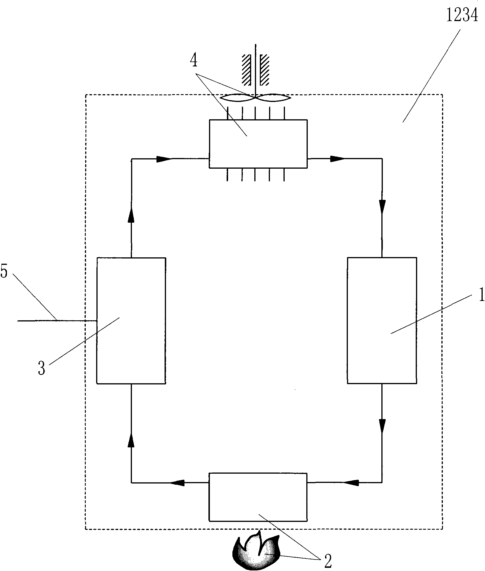
[0050] Such as figure 1 The high-efficiency hot gas engine shown comprises a compressor 1, a heater 2, an explosive discharge engine 3 and a cooler 4, and gas working medium inlets and The gas working medium outlet, the gas working medium outlet of the compressor 1 is connected with the gas working medium inlet of the heater 2, the gas working medium outlet of the heater 2 is connected with the gas working medium inlet of the explosive discharge engine 3, and the gas working medium of the explosive discharge engine 3 is connected. The working medium outlet communicates with the gas working medium inlet of the cooler 4, and the gas working medium outlet of the cooler 4 communicates with the gas working medium inlet of the compressor 1, so that the connection forms a single power unit section closing channel 1234, which is closed at the single power unit section The channel 1234 is filled with gas working medium, the explosive discharge engine 3 outputs power to the compressor ...

Embodiment 2

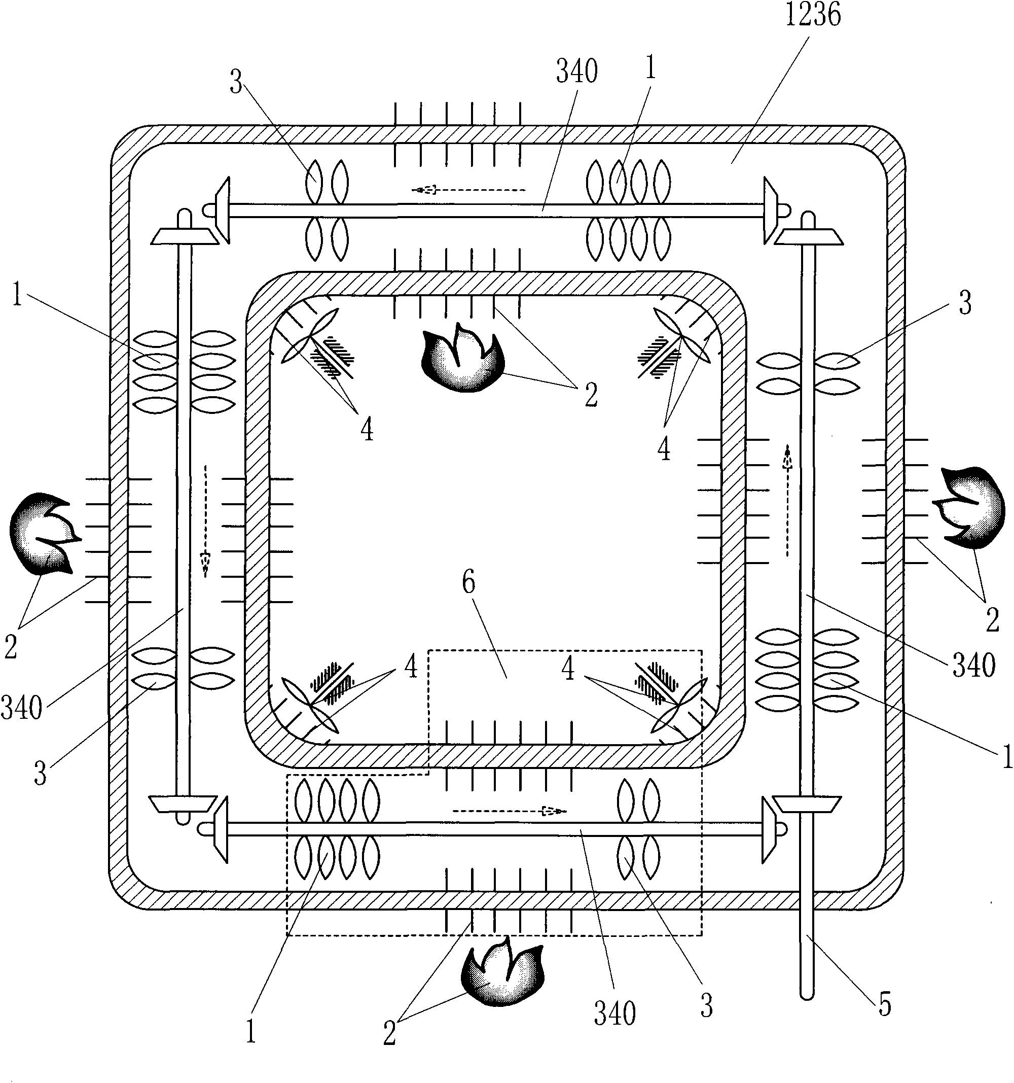
[0052] Such as figure 2 Shown high-efficiency hot gas engine, its difference with embodiment 1 is: gas working medium inlet and gas working medium outlet are set respectively on compressor 1, heater 2, explosion exhaust engine 3 and cooler 4, and the gas working medium outlet of compressor 1 The gas working medium outlet is communicated with the gas working medium inlet of the heater 2, the gas working medium outlet of the heater 2 is communicated with the gas working medium inlet of the explosive discharge engine 3, and the gas working medium outlet of the explosive discharge engine 3 is connected with the gas working medium of the cooler 4. The inlets of the working fluid are connected, so that they form a power unit section 6, n compressors 1, n heaters 2, n explosive discharge engines 3 and n coolers 4 form n power unit sections 6, n=4, The n power unit sections 6 are connected in series, and then the gas working medium outlet of the cooler 4 at one end is connected with ...

Embodiment 3

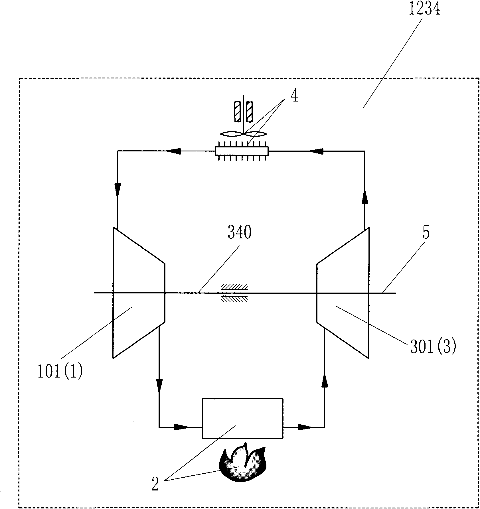
[0054] Such as image 3 The difference between the high-efficiency hot gas engine shown and Embodiment 1 is that the compressor 1 is set as an impeller compressor 101 , and the explosive exhaust engine 3 is set as a power impeller 301 . The purpose of such setting is to make full use of the advantages of high rotational speed, small volume and large flow rate of the impeller compressor 101 and the power impeller 301 .


PUM


Abstract

The invention discloses an efficient hot-air engine which comprises a gas compressor, a heater, a detonation engine and a cooler, wherein the gas compressor, the heater, the detonation engine and the cooler are respectively provided with a gas working medium inlet and a gas working medium outlet; the gas working medium outlet of the gas compressor is communicated with the gas working medium inlet of the heater, the gas working medium outlet of the heater is communicated with the gas working medium inlet of the detonation engine, the gas working medium outlet of the detonation engine is communicated with the gas working medium inlet of the cooler, and the gas working medium outlet of the cooler is communicated with the gas working medium inlet of the gas compressor, so that a single power unit mode closed channel is formed, and the single power unit mode closed channel is filled with gas working mediums; and the detonation engine is used for outputting power or circuitously outputting power to the gas compressor, and the detonation engine is directly or indirectly connected with a power output shaft. The efficient hot-air engine provided by the invention has the advantages of simple structure, high efficiency and low noise.

Description

technical field [0001] The invention relates to the field of heat energy and power, in particular to a high-efficiency heat engine. Background technique [0002] The traditional hot gas engine, i.e. the Stirling engine, is widely used, but its structure is complex, the area of ​​the heating zone and the cooling zone and the heating and cooling time are all limited. Therefore, it is urgent to invent a simple structure, high heating and cooling efficiency. , a new high-efficiency heat engine with a high ratio of power to volume. Contents of the invention [0003] In order to solve the above problems, the technical scheme proposed by the present invention is as follows: [0004] A high-efficiency hot gas engine, including a compressor, a heater, an explosion engine and a cooler, and a gas working medium inlet and a gas inlet are respectively arranged on the compressor, the heater, the explosion engine and the cooler. Working medium outlet, the gas working medium outlet of t...

Claims


Application Information

Patent Timeline
Patent Type & Authority Applications(China)
IPC IPC(8): F02G1/047F02G1/055F02G1/057F02G1/044
Inventor 靳北彪
Owner 靳北彪
Why Eureka
Try Eureka