Two-stage compression heat pump system
A two-stage compression and heat pump system technology, applied to compressors, compressors with reversible cycles, lighting and heating equipment, etc., can solve the problems that compressors cannot be used at the same time, and the initial investment of the system is high, so as to achieve small temperature difference fluctuation control , Improve system efficiency, the effect of small initial investment
- Summary
- Abstract
- Description
- Claims
- Application Information
AI Technical Summary
Problems solved by technology
Method used
Image
Examples
Embodiment 1
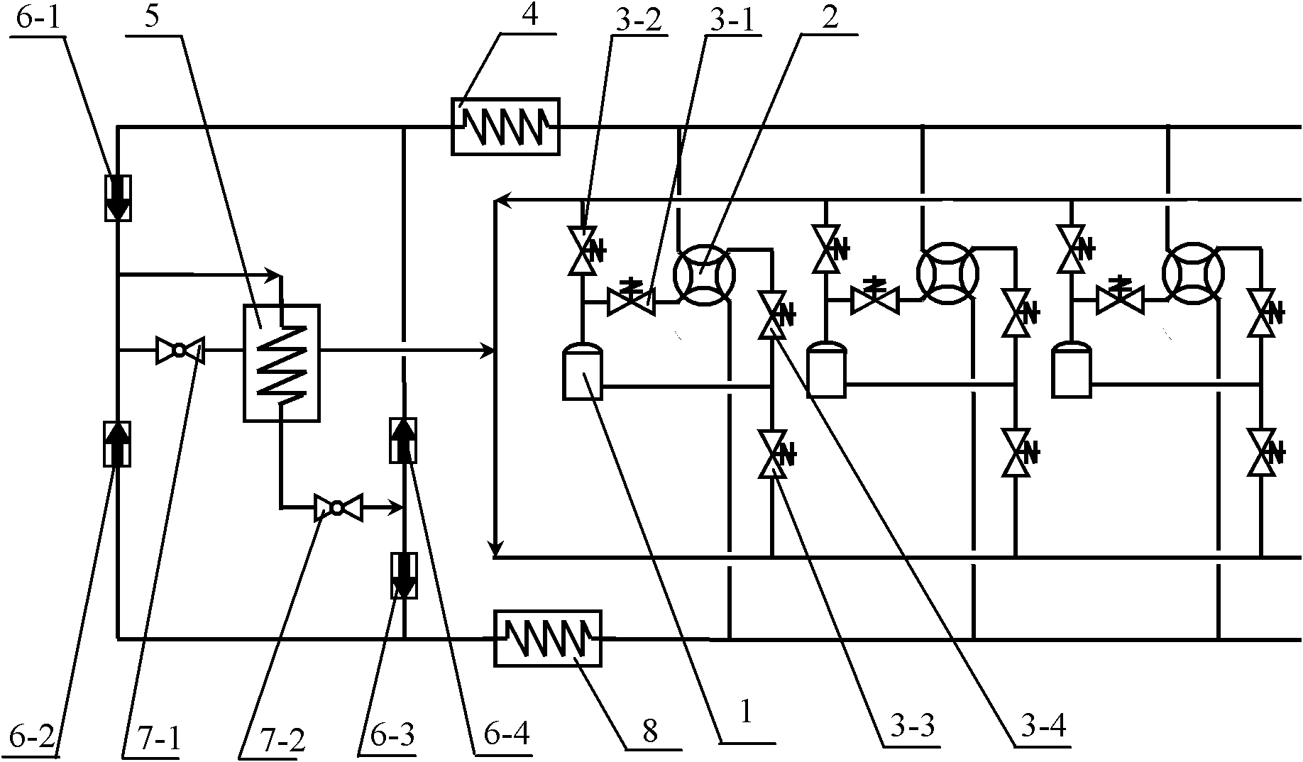
[0022] figure 1It is a schematic diagram of a two-stage compression heat pump system with one-stage throttling and incomplete cooling in the middle of the present invention, including multiple sets of compressor units, a first heat exchanger 4, a second heat exchanger 8, and an intercooler 5. The intercooler is a shell Tube heat exchanger or plate heat exchanger. Each group of compressors includes compressor 1, four-way reversing valve 2, first solenoid valve 3-1, second solenoid valve 3-2, third solenoid valve 3-3, fourth solenoid valve 3-4, compressor The exhaust end of compressor 1 is respectively connected with the first electromagnetic valve 3-1 and the second electromagnetic valve 3-2, and the suction end of compressor 1 is respectively connected with the third electromagnetic valve 3-3 and the fourth electromagnetic valve 3-4, The first solenoid valve 3-1 of each group of compressors is connected to the fourth interface 2-4 of the four-way reversing valve 2, the second...
Embodiment 2
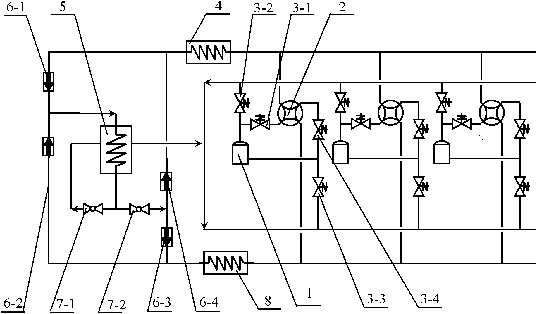
[0033] figure 2 It is a schematic diagram of another two-stage compression heat pump system with one-stage throttling and incomplete cooling in the middle, except that the connection mode of the second throttling valve is different, and the other structures are the same as in Embodiment 1. It includes multiple sets of compressor units, a first heat exchanger 4, a second heat exchanger 8, and an intercooler 5, and the intercooler is a shell-and-tube heat exchanger or a plate heat exchanger. Each group of compressors includes compressor 1, four-way reversing valve 2, first solenoid valve 3-1, second solenoid valve 3-2, third solenoid valve 3-3, fourth solenoid valve 3-4, compressor The exhaust end of compressor 1 is respectively connected with the first electromagnetic valve 3-1 and the second electromagnetic valve 3-2, and the suction end of compressor 1 is respectively connected with the third electromagnetic valve 3-3 and the fourth electromagnetic valve 3-4, The first sole...
Embodiment 3
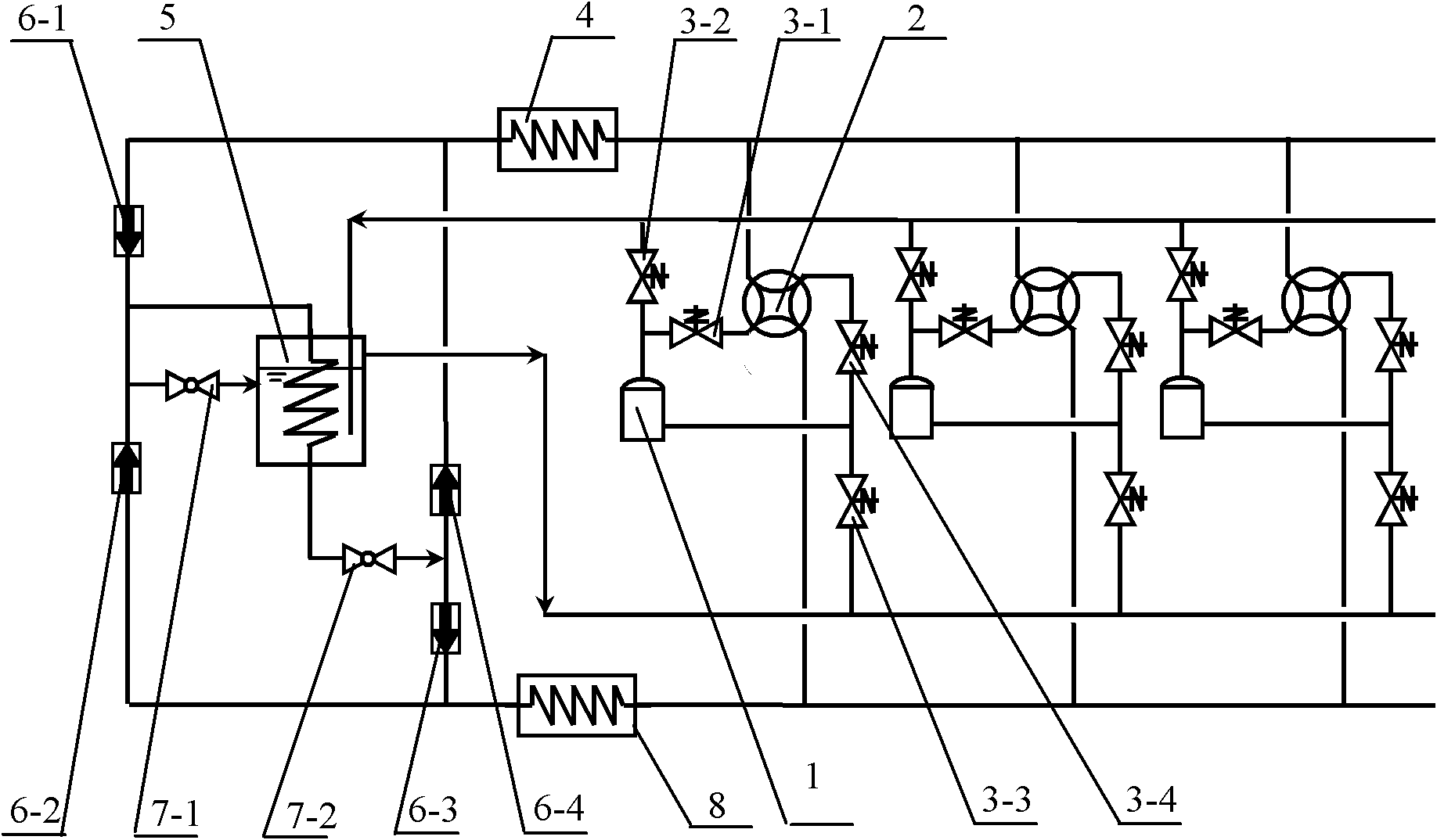
[0044] image 3 Schematic diagram of a two-stage compression heat pump system with one-stage throttling and complete cooling in the middle, including multiple sets of compressor units, the first heat exchanger 4, the second heat exchanger 8, and the intercooler 5. The intercooler is equipped with a liquid level shell and tube heat exchanger. Each group of compressors includes compressor 1, four-way reversing valve 2, first solenoid valve 3-1, second solenoid valve 3-2, third solenoid valve 3-3, fourth solenoid valve 3-4, compressor The suction end of 1 is respectively connected with the third electromagnetic valve 3-3 and the fourth electromagnetic valve 3-4, and the first electromagnetic valve 3-1 of each compressor group is connected with the fourth interface 2-4 of the four-way reversing valve 2 connection, the second solenoid valve 3-2 is connected in parallel with the shell side inlet below the liquid surface of the intercooler 5, the third solenoid valve 3-3 is connecte...
PUM
 Abstract
Description
Claims
Application Information
 - R&D
- Intellectual Property
- Life Sciences
- Materials
- Tech Scout
- Unparalleled Data Quality
- Higher Quality Content
- 60% Fewer Hallucinations
Browse by: Latest US Patents, China's latest patents, Technical Efficacy Thesaurus, Application Domain, Technology Topic, Popular Technical Reports.
© 2025 PatSnap. All rights reserved.Legal|Privacy policy|Modern Slavery Act Transparency Statement|Sitemap|About US| Contact US: help@patsnap.com


