
Battery cap assembly and battery

A battery and cap technology, which is applied in the field of battery cap components, can solve the problems of easy contact with the inner wall of the battery cylinder, the solder joints of the pull plate and the explosion-proof film falling off, and the heating of the battery, so as to avoid explosion injury and sealing Poor performance, less damage effect

Inactive Publication Date: 2011-04-27
SHENZHEN BAK BATTERY CO LTD
View PDF7 Cites 6 Cited by
  • Summary
  • Abstract
  • Description
  • Claims
  • Application Information

AI Technical Summary

Problems solved by technology

[0004] But the cap assembly of above-mentioned structure still has defect, as image 3 As shown, when the battery is sealed by flanging, the sealing ring 22 will be squeezed from the upper and lower directions (F1, F2), so that the sealing ring 22 is deformed, and then the pull plate 25 that is close to the inner ring of the sealing ring 22 The downward pressure F3 will easily cause the solder joint between the pull plate and the explosion-proof membrane to fall off, making the battery invalid
Additionally, if Figure 4 As shown, when the internal gas pressure of the battery increases and the connection point between the middle part of the pull plate 25 and the pressure protection diaphragm 24 is disconnected, the periphery of the pull plate 25 will be in a free state without fixed support points in the battery cylinder. The plate 25 is still charged. At this time, when the battery is squeezed, shaken, or collided, the pull plate 25 is likely to touch the inner wall of the battery cylinder and short-circuit it, which will further heat the battery, and even cause combustion and explosion.

Method used


Image

  • Battery cap assembly and battery
  • Battery cap assembly and battery
  • Battery cap assembly and battery

Examples


Embodiment Construction

[0027] The present invention will be further described in detail below through specific embodiments in conjunction with the accompanying drawings.

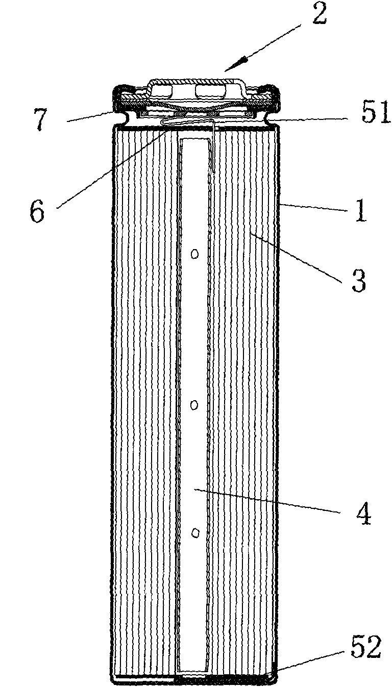
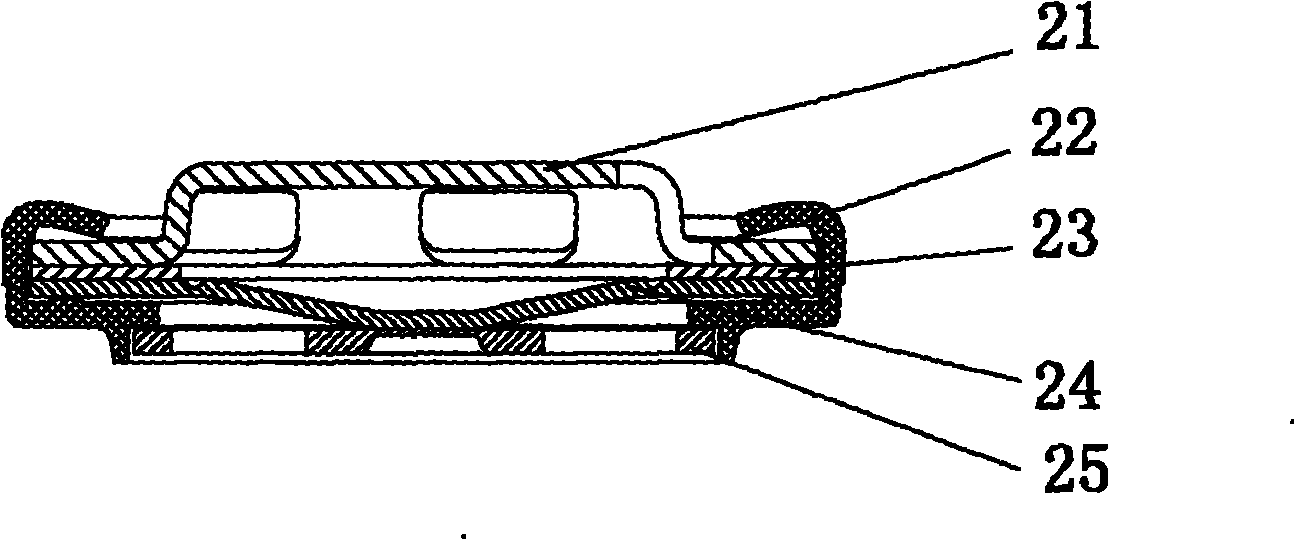
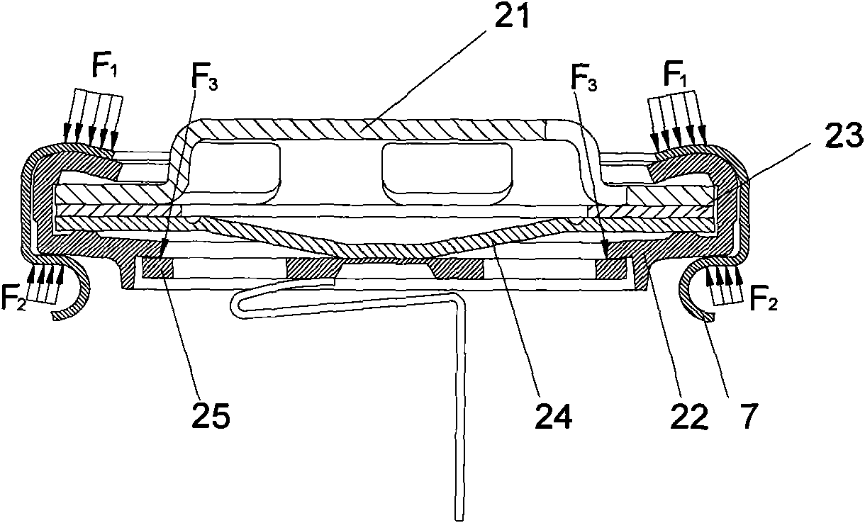
[0028] Such as Figure 5 A cylindrical lithium-ion battery shown includes: a battery cylinder 1 , a cap assembly 2 , a battery electrode group 3 , a support frame 4 , electrode lead terminals, and a top spacer 6 .

[0029] The battery electrode group 3 and the support frame 4 are arranged in the cavity of the cylinder body 1 . The electrode lead-out terminals include a positive / negative lead-out terminal 51 disposed above the battery pole group 3 and a negative / positive lead-out terminal 52 disposed below the battery pole group 3 . The positive / negative lead-out terminal 51 is electrically connected to the battery cap assembly 2, and the negative / positive lead-out terminal 52 is electrically connected to the inner wall of the battery cylinder. The upper and lower ends of the battery pole group 3 are provided with top spacers 6, ...


PUM


Abstract

The invention discloses a battery cap assembly and a battery. The battery cap assembly comprises a top plate, a pressure protection diaphragm, a pull plate fixing ring and a pull plate, which are sequentially arranged from top to bottom, and also comprises sealing rings covering the peripheries of the top plate and the pressure protection diaphragm; the periphery of the pressure protection diaphragm is provided with a fixed part which is electrically connected with the top plate; the middle part of the pressure protection diaphragm is provided with a downwardly bent elastic part which is electrically connected with the middle part of the pull plate; and the pull plate fixing ring is arranged between the periphery of the pressure protection diaphragm and the periphery of the pull plate to ensure that the upper surface of the periphery of the pull plate resists against the lower surface of the pull plate fixing ring. By means of the structure, when the pull plate is released from a welding point of the pressure protection diaphragm, the pull plate does not move freely to make contact with the inner wall of a cylinder of the battery to cause short circuit, thereby improving the security of the battery. When the battery is sealed or normally used, the collision, the swaying and the damage of an electric connection point on the pull plate due to the deformation of the sealing rings are prevented.

Description

technical field [0001] The invention relates to a battery, in particular to a battery cap assembly. Background technique [0002] With the development of technology and the improvement of social requirements for product quality, lithium-ion battery development technology has evolved to include more auxiliary components in the battery structure, for example, safety devices are designed in the battery. However, the development of these technologies has also increased the complexity of the battery, which in turn has increased the reliability problem of the battery and the possibility of battery failure. The cap assembly of the lithium-ion battery is one of the key components in the structure of the lithium-ion battery. In the prior art, the safety structure of the battery is generally set in the cap assembly, which is related to the reliability and safety of the product and affects the The personal safety of producers and users. [0003] A known structure of a cylindrical lit...

Claims


Application Information

Patent Timeline
IPC IPC(8): H01M2/04H01M2/12H01M2/20H01M2/08H01M2/34H01M10/36H01M2/26
CPCY02E60/12Y02E60/10
Inventor 陈保同
Owner SHENZHEN BAK BATTERY CO LTD
Features
  • Generate Ideas
  • Intellectual Property
  • Life Sciences
  • Materials
  • Tech Scout
  • Unparalleled Data Quality
  • Higher Quality Content
  • 60% Fewer Hallucinations
Learn More