
High spatial resolution imaging of a structure of interest in a specimen

A technology with a structure of interest and spatial resolution, which can be used in the analysis of materials, material excitation analysis, material analysis by optical means, etc., and can solve the problem that fluorescent dyes cannot fluoresce.

Active Publication Date: 2011-04-27
MAX PLANCK GESELLSCHAFT ZUR FOERDERUNG DER WISSENSCHAFTEN EV
View PDF3 Cites 9 Cited by
  • Summary
  • Abstract
  • Description
  • Claims
  • Application Information

AI Technical Summary

Problems solved by technology

However, in order to obtain the high spatial resolution achievable by the aforementioned methods for imaging structures of interest, strong limitations due to switchable proteins or fluorophores have to be tolerated.
[0008] In so-called GSD (ground state depletion) microscopy (S. Bretschneider et al. in Phys. Rev. Lett. 98, 218103 (2007) published in the article titled "Breaking the diffraction barrier in fluorescence microscopy by optical shelving" ), the diffraction limit for imaging structures labeled by fluorescent dyes in the sample is overcome by converting the respective fluorescent dye located outside the respective measurement point from its electronic ground state to a dark electronic state, where in the electronic ground state, the respective fluorescent dye Can be excited to fluoresce by excitation light, and in the dark electronic state, the fluorochrome cannot fluoresce

Method used


Image

  • High spatial resolution imaging of a structure of interest in a specimen
  • High spatial resolution imaging of a structure of interest in a specimen
  • High spatial resolution imaging of a structure of interest in a specimen

Examples


Embodiment Construction

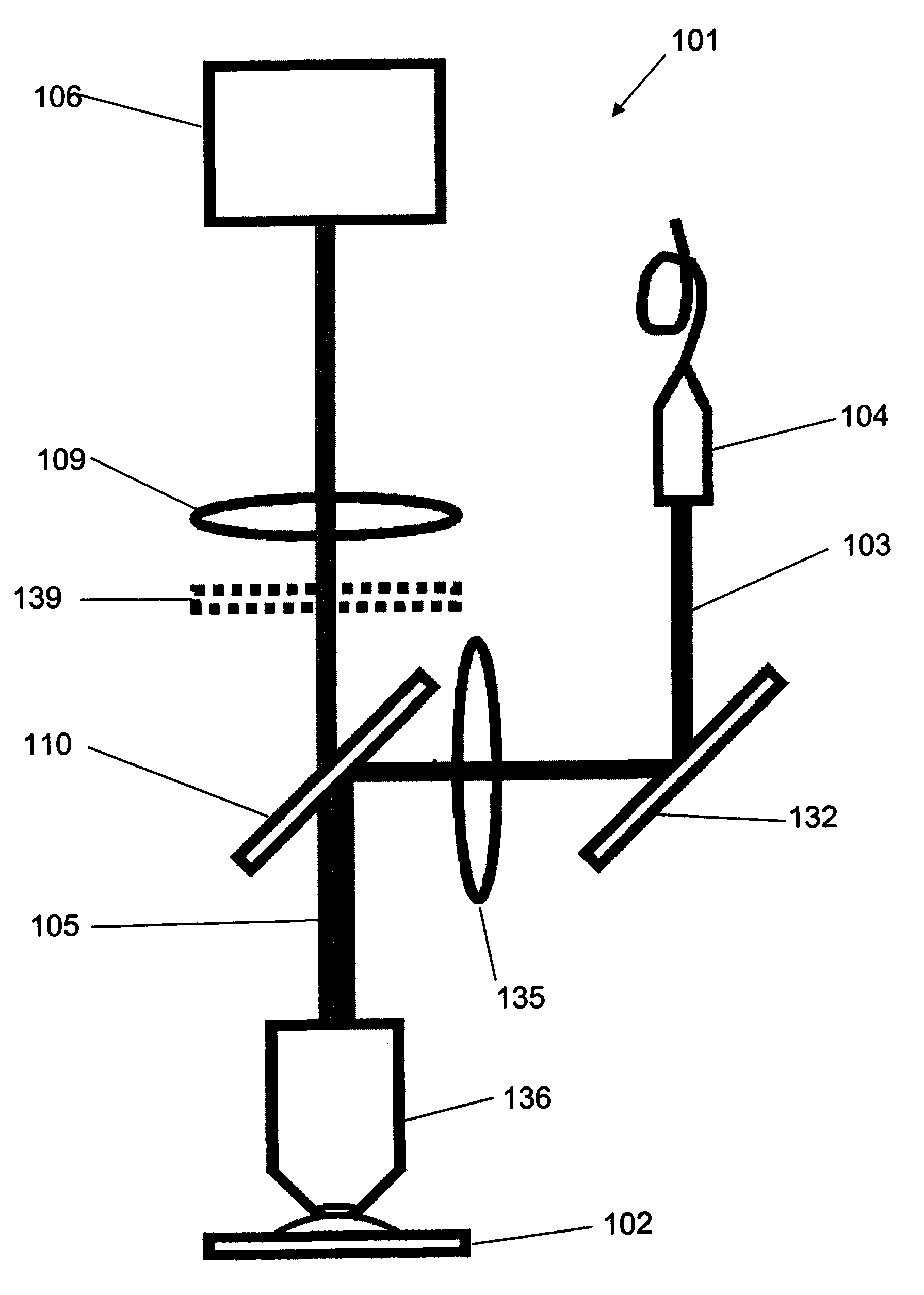
[0035] Reference will now be made in more detail to the accompanying drawings. figure 1 A fluorescence microscope 101 is schematically illustrated. When performing high spatial resolution imaging of structures of interest in a sample 102 with a fluorescence microscope 101 according to the present invention, light 103 with one wavelength (black line) from a light source 104 is provided via a mirror 132, and the light 103 utilizes Lens 135 focuses into objective lens 136 . Light 103 is used for large area illumination of the entire region of interest in sample 102 . Fluorescence 105 (gray line) from a fluorochrome in the sample 102 is likewise collected by the objective, in this case the same objective 6, and separated from the light 103 by means of a dichroic mirror 110 and, if desired, by a suitable Fluorescence filter 139 further filters. In combination with objective lens 135 , lens 109 ensures proper imaging of fluorescent molecules of the fluorescent dye on sensor array...


PUM


Abstract

For high spatial resolution imaging of a structure of interest in a specimen, a substance is selected from a group of substances which have two different electronic states: a fluorescent first state and a nonfluorescent second state; which can be converted fractionally from their first state into their second state by light which excites them into fluorescence, and which return from their second state into their first state; the specimen's structure of interest is imaged onto a sensor array, a spatial resolution limit of the imaging being greater (i.e. worse) than an average spacing between closest neighboring molecules of the substance in the specimen; the specimen is exposed to light in a region which has dimensions larger than the spatial resolution limit, fractions of the substance alternately being excited by the light to emit fluorescent light and converted into their second state, and at least 10% of the molecules of the substance that are respectively in the first state lying at a distance from their closest neighboring molecules in the first state which is greater than the spatial resolution limit; and the fluorescent light, which is spontaneously emitted by the substance from the region, is registered in a plurality of images recorded by the sensor array during continued exposure of the specimen to the light.

Description

technical field [0001] The invention relates to a method for high spatial resolution imaging of structures of interest in a sample, said method comprising the features of the preamble of claim 1 . Background technique [0002] WO 2006 / 127692 A2 discloses a method for high spatial resolution imaging of structures of interest in a sample, wherein the structures of interest are imaged using switchable fluorescent dyes in the form of so-called phototransformable optical labels. mark. A labeled subgroup is respectively activated to a state in which the labeled subgroup can be excited to emit fluorescence. The respective subset includes so few markers that the markers are located at a distance from each other greater than the spatial resolution limit for imaging the sample onto the sensor array. This enables, after excitation of a subset of labels to fluoresce, to localize the initial position of fluorescence with better resolution than the diffraction limit of the spatial resol...

Claims


Application Information

Patent Timeline
IPC IPC(8): G01N21/64
CPCG02B27/58G02B21/16G01N21/6458G01N21/6428G02B21/367
Inventor J·弗林C·埃格林A·艾格纳A·舍恩勒M·博西S·黑尔
Owner MAX PLANCK GESELLSCHAFT ZUR FOERDERUNG DER WISSENSCHAFTEN EV
Learn More