Manufacturing process of high-precision extrusion die for DeNOx catalyst

A denitration catalyst and extrusion die technology, which is applied in the field of mechanical manufacturing and processing technology, can solve the problems of increased cost, high difficulty in processing and manufacturing, and high scrap rate, and can avoid size and position tolerances, process stable and reliable, and shorten production cycles. Effect

Active Publication Date: 2011-05-04
CHONGQING YUANDA CATALYST MFG
View PDF4 Cites 20 Cited by
  • Summary
  • Abstract
  • Description
  • Claims
  • Application Information

AI Technical Summary

Problems solved by technology

[0002] The denitrification catalyst is the core and key of the SCR flue gas denitrification system. The denitrification catalyst is generally made by extruding a mold. In order to achieve a higher utilization rate, the wall thickness and specific surface area of ​​the denitrification catalyst must meet higher requirements, and the catalyst Generally, it has a complex multi-deep hole structure, which determines that the extrusion die also has a complex structure and high manufacturing difficulty.
[0003] A single deep hole (groove) can be processed by the existing mechanical processing technology, and the tolerance requirement in the range of 0.01 mm can generally be achieved. It is very difficult to process and ensure that it meets the technical requirements, and it is very easy to cause the processed workpiece to be scrapped.
Due to the high price of the base material of the extrusion die of the catalyst and the complex structure (the number of deep holes (grooves) is large), once a certain hole (groove) has an out-of-tolerance size or position, the entire workpiece will be scrapped, and the scrap rate is high. Leading to a substantial increase in cost and lengthening of the manufacturing cycle

Method used


Image

  • Manufacturing process of high-precision extrusion die for DeNOx catalyst
  • Manufacturing process of high-precision extrusion die for DeNOx catalyst
  • Manufacturing process of high-precision extrusion die for DeNOx catalyst

Examples


Embodiment Construction

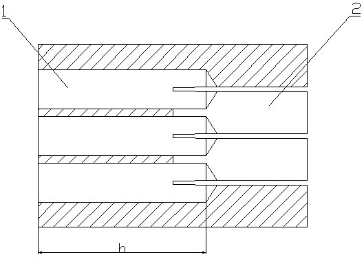
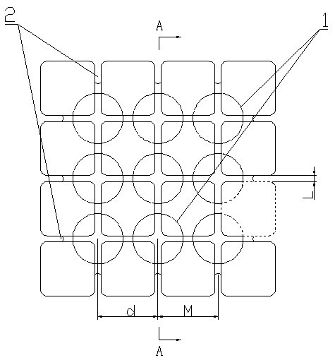
[0025] Using the denitrification catalyst high-precision extrusion die manufacturing process of this embodiment for example figure 1 and figure 2 The extrusion dies shown are processed:

[0026] a. It is required to process 9 holes of Φ6.8-0.015mm on a plane of 50×50mm, and ensure that the center distance is 12.725±0.015mm, and the hole depth is 45mm -0.01 mm, the surface roughness is less than Ra0.8;

[0027] b. It is required to process grooves with a groove width of 0.9±0.01mm and a center distance of 12.725±0.015mm on a plane with a boss of 50×50mm, which are respectively connected to the 9 holes in a. The symmetry is required to be 0.01 Within mm, the surface roughness is less than Ra0.8.

[0028] The specific implementation process includes the following steps:

[0029] 1) Cutting: According to the requirements of the drawings, lay down the cuboid blank, leave a machining allowance of 3 mm on each of the four faces parallel to the longitudinal direction, and leave a...


PUM


Abstract

The invention discloses a manufacturing process of a high-precision extrusion die for a DeNOx catalyst. The manufacturing process comprises the following steps: discharging, thermal refining, grinding, rough machining, grinding, boring holes, semi-fine grinding, thermal treatment, groove linear cutting, benching, fine grinding and protective treatment. In the process, by means of the methods such as reasonable control of machining amount, reasonable selection of equipment parameters and the like in the steps, the surface roughness, the dimensional precision and the form and position accuracy of holes (grooves) of machined parts of the extrusion die with multiple deep holes (grooves) for the catalyst are effectively ensured, wherein, the machining precision reaches 0.01mm, and the surface roughness reaches over Ra0.8; the machining process is stable and reliable; the qualification rate of the die product reaches over 99%; and the difficulty in manufacturing the complicated die with the multiple deep holes (grooves) is overcome. Compared with the prior art, the manufacturing process disclosed by the invention has the advantages of effectively avoiding scrap caused by size and location out-of-tolerance, greatly lowering production cost, improving machining efficiency and shortening production cycle.

Description

technical field [0001] The invention relates to a mechanical manufacturing process, in particular to a mold manufacturing process. Background technique [0002] The denitrification catalyst is the core and key of the SCR flue gas denitrification system. The denitrification catalyst is generally made by extruding a mold. In order to achieve a higher utilization rate, the wall thickness and specific surface area of ​​the denitrification catalyst must meet higher requirements, and the catalyst It generally has a complex multi-deep hole structure, which determines that the extrusion die also has a complex structure and high manufacturing difficulty. [0003] A single deep hole (groove) can be processed by the existing mechanical processing technology, and the tolerance requirement in the range of 0.01 mm can generally be achieved. It is very difficult for processing technology to process and ensure that it meets the technical requirements, and it is very easy to make the proces...

Claims


Application Information

Patent Timeline
Patent Type & Authority Applications(China)
IPC IPC(8): B23P15/24
Inventor 樊永生陈晓平刘洪辉周林刘显彬黄锐邱永志周敏刘强张河坤唐武
Owner CHONGQING YUANDA CATALYST MFG
Why Eureka
Try Eureka