Thermocompressor driven by linear motors

A technology of thermal compressors and linear motors, which is applied in the direction of machines/engines, mechanical equipment, liquid variable capacity machinery, etc. It can solve the problems of easy deviation from the central axis of the air gap, unfavorable smooth operation of the compressor, and unstable movement of the compressor, etc. Problems, to achieve the effect of small vibration, force balance, and reduce mechanical vibration

Inactive Publication Date: 2011-05-04
TECHNICAL INST OF PHYSICS & CHEMISTRY - CHINESE ACAD OF SCI
View PDF0 Cites 12 Cited by
  • Summary
  • Abstract
  • Description
  • Claims
  • Application Information

AI Technical Summary

Problems solved by technology

Compared with other linear motors of the same volume, the moving iron linear motor can generate a larger driving force, and the compression ratio of the compressor made of it is also larger, but the movement of this compressor in the air gap is not stable , it is easy to deviate from the central axis of the air gap, which is not conducive to the smooth operation of the compressor

Method used


Image

  • Thermocompressor driven by linear motors
  • Thermocompressor driven by linear motors
  • Thermocompressor driven by linear motors

Examples


Embodiment Construction

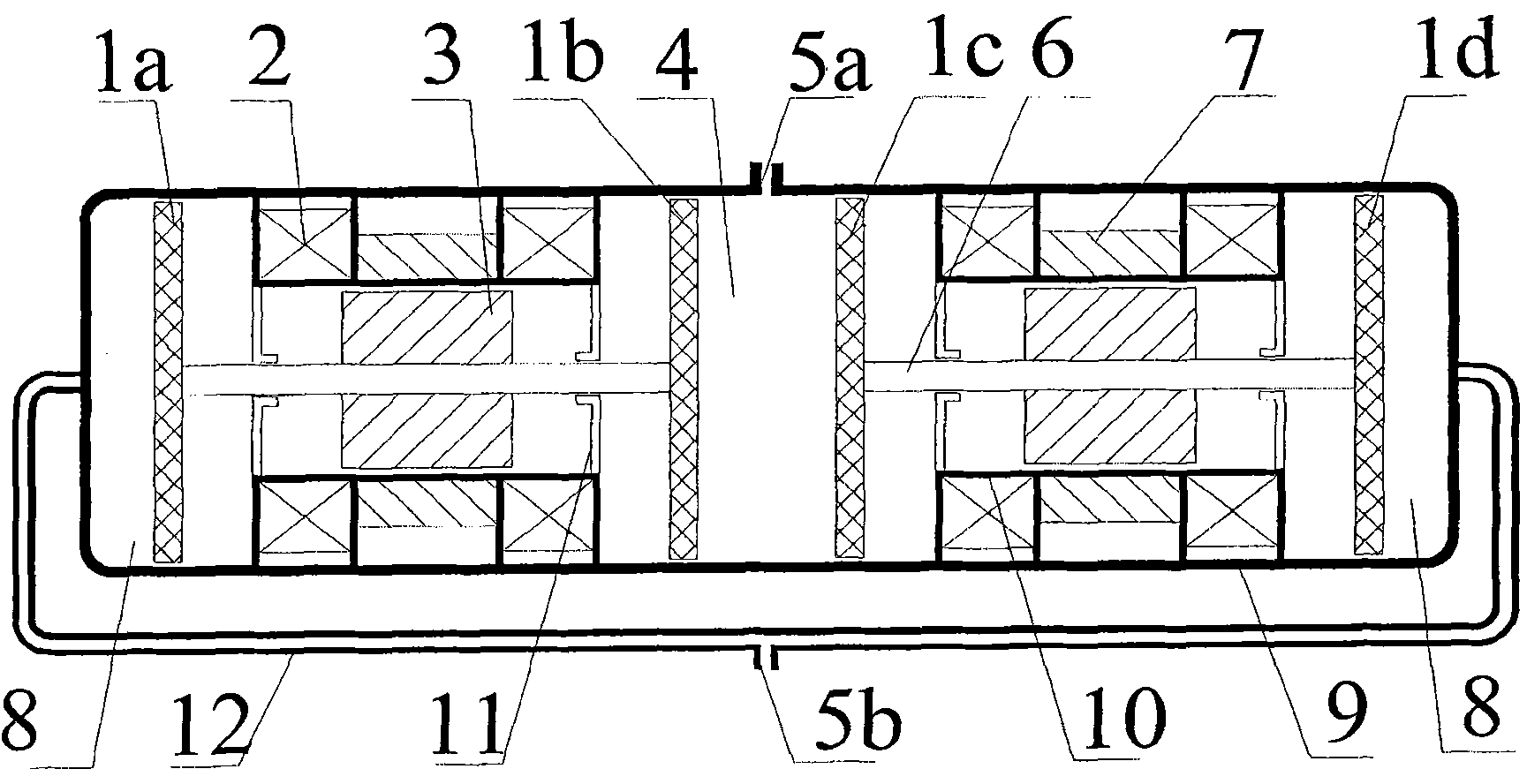
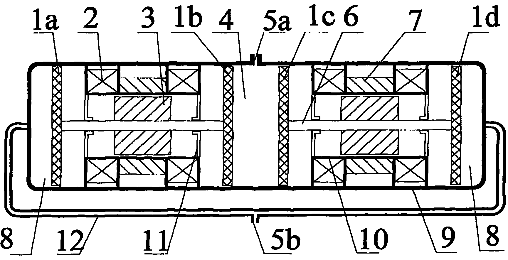
[0017] see figure 1 , which is a schematic diagram showing the structure of the driving unit of the thermal compressor in one embodiment of the present invention. In this embodiment, the linear motor is a moving iron type oscillating motor. As shown in the figure, the drive unit includes a cylinder 9 and a linear motor-piston assembly disposed in the cylinder, wherein two identical linear motor-piston assemblies each having a double-headed piston are symmetrical with respect to the radial center line of the cylinder 9 Arrangement, the piston heads 1b, 1c facing each other of the double-headed pistons of the two linear motor-piston assemblies together with the cylinder wall define the first working chamber 4 in the middle of the cylinder, and the piston heads 1a, 1d away from each other are at the two ends of the cylinder and The cylinder walls together define the second working chamber 8, the first communicating pipe 12 connects both ends of the cylinder wall, the first worki...


PUM


Abstract

The invention discloses a thermocompressor. The thermocompressor comprises a driving unit, and a first cooler (13), a heat regenerator (14), a heater (15), a pulse tube (16) and a second cooler (17) which are connected in turn, wherein the driving unit comprises a cylinder (9) and linear motor-piston components which are arranged in the cylinder. Two same linear motor-piston components which are provided with double-ended pistons respectively are symmetrical relative to a radial centerline of the cylinder; a first communicating tube (12) communicates two ends of a wall of the cylinder; a first working chamber (4) is communicated with the first cooler through a first outlet (5a); a second working chamber (8) is communicated with the second cooler through a second outlet (5b); two linear motors drive the two double-ended pistons to reciprocate reversely in the cylinder respectively to drive a pulse tube refrigerator to work. The linear motors are symmetrical, so that the air displacement is large, the inertia forces of the pistons when the pistons move are balanced, and the pistons have small vibration when running; and the front and back differential pressures of the pistons are the same to facilitate reducing mechanical vibration.

Description

technical field [0001] The present invention relates to thermal compressors, and more particularly to thermal compressors driven by linear motors. Background technique [0002] Thermal compressor technology is derived from Stirling engine technology, which is an external combustion, closed-cycle heat engine. Its ideal thermodynamic cycle is called a generalized Carnot cycle, so its theoretical efficiency is high at the same temperature. It has two obvious advantages: First, it can utilize various energy sources, whether it is commonly used liquid fuel, gas fuel or solid fuel, or even waste heat, solar energy, chemical reaction energy and radioisotope energy, as long as it can generate heat at a certain temperature , the thermal compressor can work; the second is low vibration and noise, low emission pollution, and has good environmental characteristics. It has great advantages in cogeneration of heat, power and cooling, comprehensive utilization of solar energy, and recycli...

Claims


Application Information

Patent Timeline
Patent Type & Authority Applications(China)
IPC IPC(8): F04B35/04
Inventor 杨鲁伟吕君吴小华王厚生周远
Owner TECHNICAL INST OF PHYSICS & CHEMISTRY - CHINESE ACAD OF SCI
Why Eureka
Try Eureka