Non-nail clamped electric heating floor system and electric heating floors thereof

A technology of electric heating floor and electric heating plate, which is applied in the field of building decoration, and can solve problems such as hidden safety hazards, cracking, and affecting heating

Inactive Publication Date: 2011-05-04
葛跃进
View PDF11 Cites 29 Cited by
  • Summary
  • Abstract
  • Description
  • Claims
  • Application Information

AI Technical Summary

Problems solved by technology

The disadvantage of this electric heating floor system is that the power supply method using plugs and sockets between adjacent floors is unreliable. This is because the thickness of the floor is usually not more than 1.2 cm. Special plugs and sockets, even if the distance between the plugs and sockets is very short, a little carelessness will cause poor contact, which will not only affect normal heating, but also cause safety hazards
The electric heating floors in this document are powered in parallel. Although the failure of one electrical connection will cause the failure of all floors or a row of floor electrical connections at the same time, the power connection lines of all floors are connected in parallel. On the one hand, the requirements for connecting the power lines are relatively high, and the workload is relatively large; The electric heating floor uses polyurethane glue to bond the epoxy resin to the base layer of the solid wood floor and the solid wood panel layer. Since the materials bonded together are different, their respective thermal expansion and contraction rates are also different, so when the temperature changes can cause cracking between the layers

Method used


Image

  • Non-nail clamped electric heating floor system and electric heating floors thereof
  • Non-nail clamped electric heating floor system and electric heating floors thereof
  • Non-nail clamped electric heating floor system and electric heating floors thereof

Examples


Embodiment 1

[0066] (Example 1, electric heating floor)

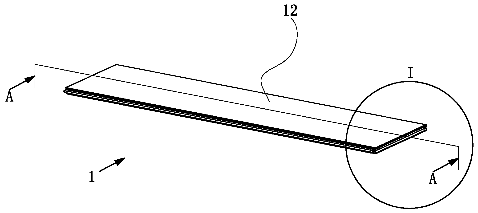
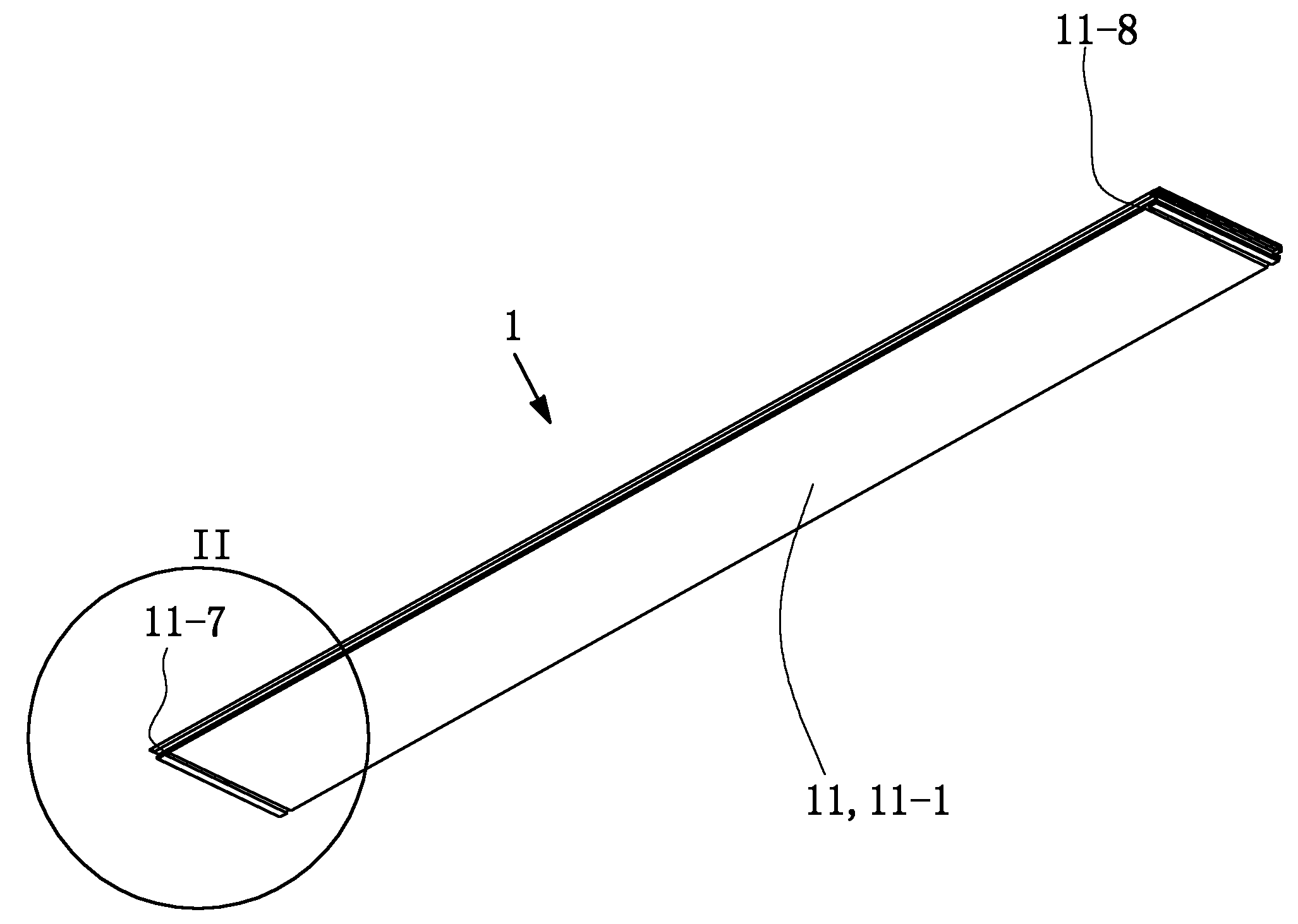
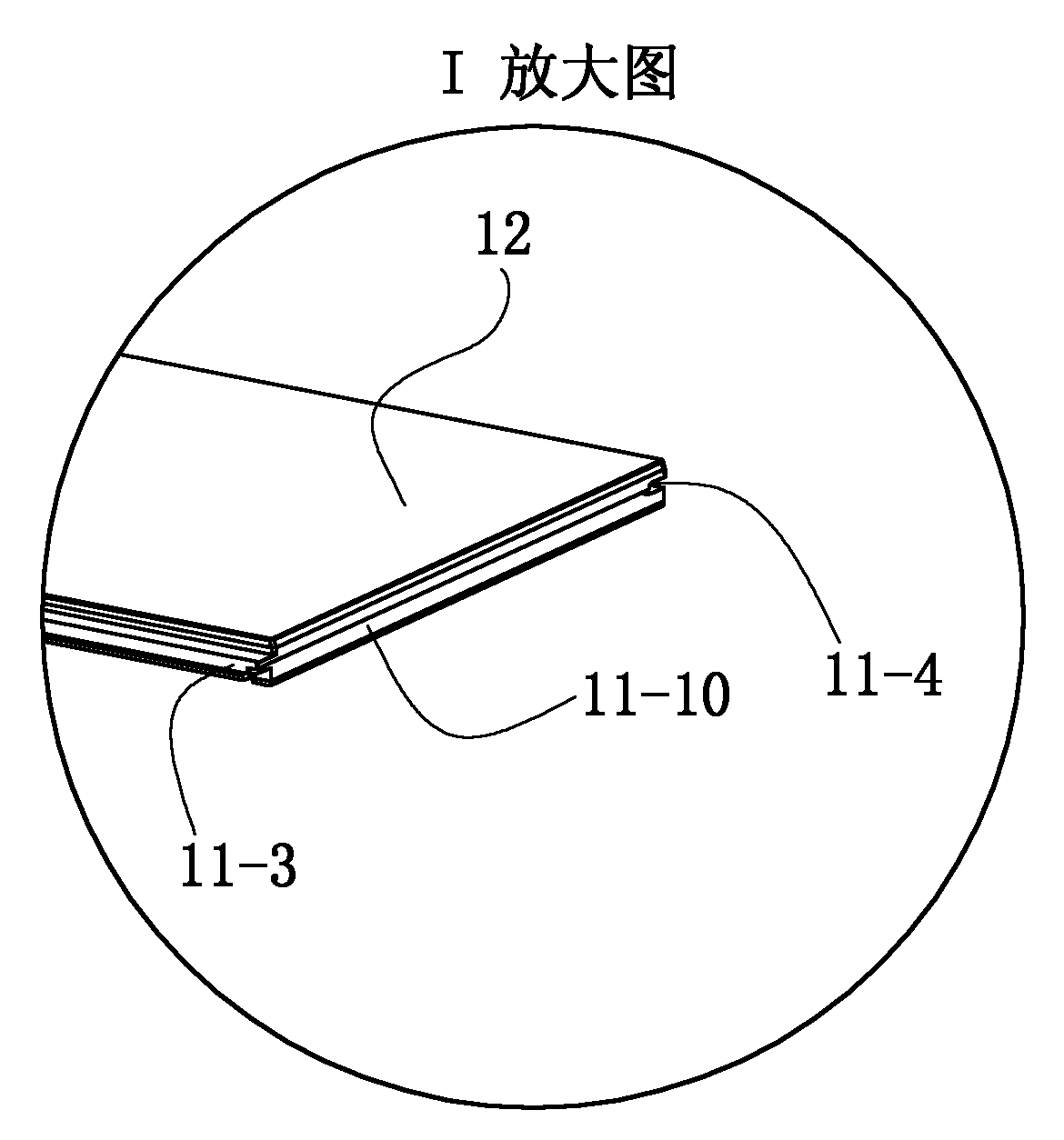
[0067] See Figure 8 and Figure 9 , The electric heating floor 1 of this embodiment includes a lower body 11 , an upper panel 12 , a carbon crystal electric heating plate 13 and a socket assembly 14 .

[0068] See figure 2 , Figure 4 and Figure 5 , the lower main body 11 is a homogeneous piece of wood, including a main body 11-1 with a basic shape of a cuboid, a tenon 11-3 located on the front side of the main body 11-1 and a tenon located on the rear side of the main body 11-1. The socket slot 11-4 and the socket tenon 11-3 are the parts for connecting and cooperating with the socket slots of the electric heating floor adjacent to the front side during use, and the socket slot 11-4 is the electric heating floor adjacent to the rear side during use. The joints and tenons of the floor are connected with each other.

[0069] The lower body 11 is also provided with a heating plate groove 11-2, a socket hole 11-5 at the left e...

Embodiment 2

[0075] (Embodiment 2, electric heating floor system installed without nails)

[0076] See Figure 10 , Figure 12 , Figure 13 , Figure 17 and Figure 22 In this embodiment, when describing the electric heating floor system without nails, the front and rear, left and right, and up and down directions are the same as those described in Embodiment 1, that is, the Figure 10 The length direction of the middle mounting base 2 is the front-to-back direction, with Figure 13 The width direction of the middle power supply keel 3 is the front-to-back direction, that is, Figure 10 The lower left in the middle is the front side, the upper right is the rear side, and the Figure 12 The up, down, left, and right directions of are the described up, down, left, and right directions.

[0077] See Figure 22 to Figure 25 , The nail-free clamping electric heating floor system of this embodiment includes an electric heating floor, an installation seat 2 and a power supply keel 3 . Wh...

Embodiment 3)

[0097] The rest of this embodiment is the same as Embodiment 2, the difference is that this embodiment is described according to a larger room, that is, the length of the mounting base 2 is described as being smaller than the length of the room, so the mounting base 2 of this embodiment is described in In actual use, several mounting bases 2 need to be spliced ​​end to end in order to form a mounting base group equal to the length of the room to be laid, that is, among the two adjacent mounting bases 2, if the mounting base located on the rear side 2 is the middle transverse positioning part 22, then the rear end of the mounting seat 2 on the front side is the corresponding plate end transverse clamping part 21, if the front end of the mounting seat 2 on the rear side is the plate end transverse clamping part 21 , then the rear end of the mounting base 2 on the front side is the corresponding middle transverse positioning portion 22, so that the mounting base group is equivalen...


PUM


Abstract

The invention discloses a non-nail clamped electric heating floor system which is characterized by comprising electric heating floors, mounting bases, power supply keels, inserting piece clips, copper conductors, connecting pieces and connecting wires. The installation method of the non-nail clamped electric heating floor system comprises the following steps: firstly the power supply keels are laid on the floor along the side of the rear wall of the laid room in the length direction; the mounting bases are laid on the floor in the mode that the length direction of the mounting bases are perpendicular to that of the power supply keels, the mounting bases are parallel to one another, and plate-end transverse clamping parts and middle transverse locating parts of two neighboring mounting bases are correspondingly arranged at front and back positions; the electric heating floors are vertically fixed on the mounting bases; and finally the electric heating floors work in parallel, i.e. all the electric heating floors emit heat for warming purpose while switching on a power supply, and other electric heating floors are not affected even though certain floor is damaged.

Description

technical field [0001] The invention relates to the field of architectural decoration, in particular to an electric heating floor system and the electric heating floor. Background technique [0002] At present, the electric heating floor has become a new heating method, which is to lay the electric heating material under the floor, and heat the floor by heating the electric heating material. [0003] Chinese patent document CN1034826C (application number 92114554.3) discloses an electric heating floor. The floor is provided with two through holes in the horizontal direction in the floor board, and the electric heating wire is inserted into the through hole. The holes are dislocated and the heating wire is worn off, and the port of the through hole adopts a bell mouth. In order to be safer, the floor boards can be added with flame retardant materials, or the floor boards can be pressed with wood powder, asbestos powder and appropriate amount of adhesive. Although this docum...

Claims


Application Information

Patent Timeline
Patent Type & Authority Applications(China)
IPC IPC(8): F24D13/02E04F15/024
Inventor 葛跃进
Owner 葛跃进
Why Eureka
Try Eureka