Pelvic band

A pelvic girdle and hip bone technology, applied in medical science, orthopedic corsets, etc., can solve problems such as difficulty in widespread popularization, increase in device prices, and inability to adjust the installation position to the degree of rehabilitation, and achieve simplified structure and low cost Effect

Inactive Publication Date: 2011-05-04
HIROSHIMA UNIVERSITY
View PDF6 Cites 3 Cited by
  • Summary
  • Abstract
  • Description
  • Claims
  • Application Information

AI Technical Summary

Problems solved by technology

For this reason, the installation position cannot be adjusted according to the patient's paralysis state and degree of rehabilitation
[0009] Since the driving unit of the above-mentioned walking assisting device has an electric motor with a reducer built in, it is necessary to install a control device and a power supply, which increases the price of the device and makes it difficult to spread widely.

Method used


Image

  • Pelvic band
  • Pelvic band
  • Pelvic band

Examples


no. 1 approach

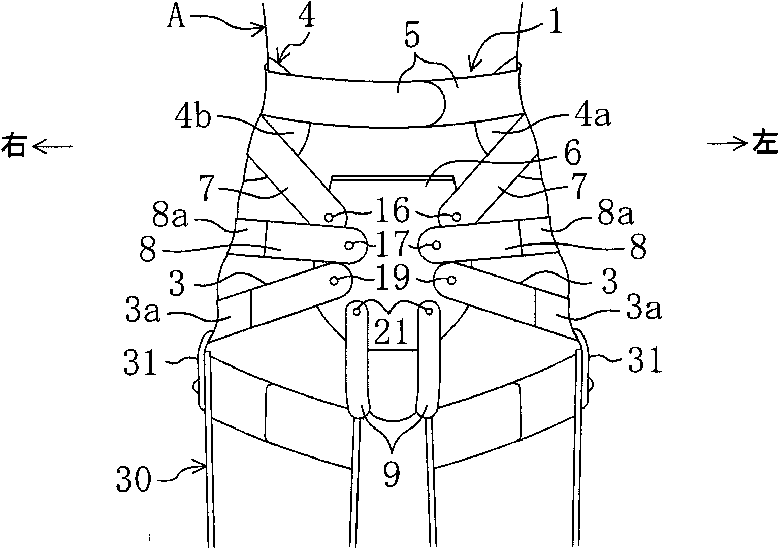
[0047] Figure 3 to Figure 5 Shown is the state of use of the pelvic girdle 1 according to the first embodiment of the present invention. The pelvic girdle 1 is used, for example, when a patient A who has difficulty walking due to paralysis or the like performs rehabilitation training. In the description of this embodiment, first, the anatomical structure from the human pelvis to the femur will be described, and then the structure and usage of the pelvic girdle 1 will be described.

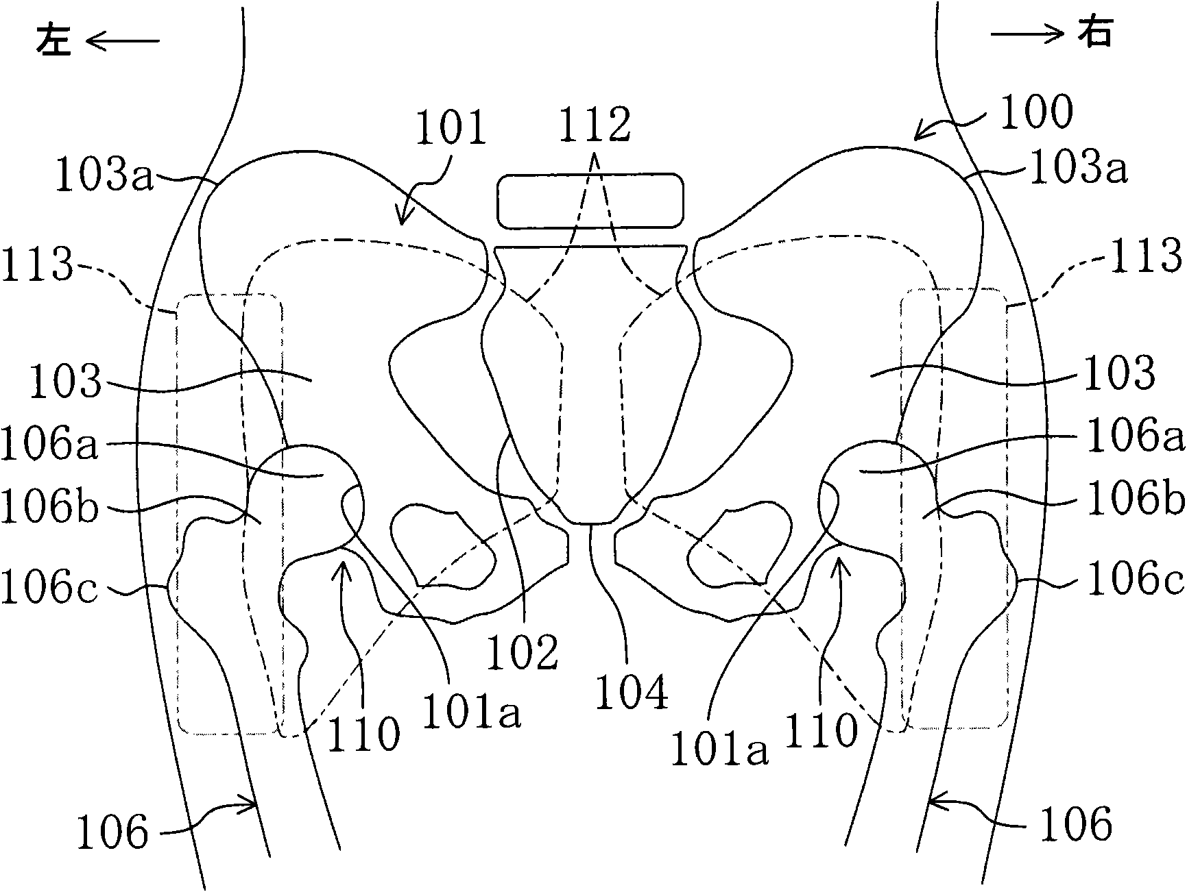
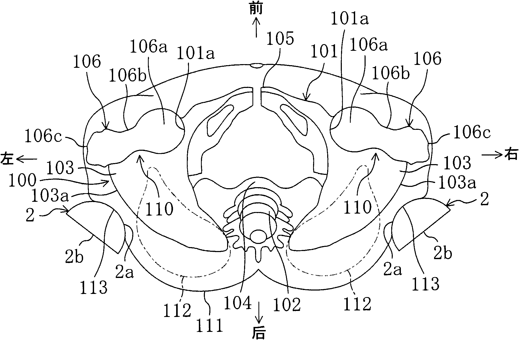
[0048] Such as figure 1 As shown, the pelvis 100 is composed of a hipbone 101, a sacrum 102 behind the central portion in the left-right direction, and a coccyx (not shown) at the front of the central portion. Hip bone 101 is by ilium 103, ischium 104 and pubic bone 105 ( figure 2 shown) are combined. The ilium 103 has ilium wings 103a protruding left and right.

[0049] The hip bone 101 has an acetabulum 101a enclosing a femoral head 106a located at the proximal end of the femur 106, and th...

no. 2 approach

[0076] Figure 7 to Figure 9 Shown is a state of use of the pelvic girdle 40 according to the second embodiment of the present invention. The difference between the pelvic girdle 40 of the second embodiment and the pelvic girdle of the first embodiment is that the pelvic girdle 40 of the second embodiment does not have the pelvis rear support plate 4, the plate fixing belt 5, the pubic support plate 6, Connection belt 7, hip joint lateral support belt 8 and perineum belt 9. This pelvic girdle 40 is used for a patient B whose symptoms are milder than those of the patient A using the pelvic girdle 1 of the first embodiment.

[0077] That is, if Figure 8 and Figure 9 As shown, the pelvic girdle 40 of the second embodiment is composed of one compression body 2 and a compression body fixing belt 41, and is suitable for rehabilitation training of a patient B with paralysis of only one lower limb. In this second embodiment, the case of the patient B who has paralysis of the lef...


PUM


Abstract

Disclosed is a pelvic band (1) that includes compression members (2) disposed to the rear of the hip joints of a patient (A), and a compression member-securing band (3) formed in such a way as to wind around a region corresponding to the pelvis (100) of the patient (A). The compression members (2) are secured in such a way as to press against the hip joints. This inhibits dropping of the hip joints rearward when the patient is walking and encourages a walking posture that better approaches a normal walking posture.

Description

technical field [0001] The present invention relates to, for example, a pelvic girdle attached to a patient who has difficulty walking due to paralysis or the like. Background technique [0002] For example, patients suffering from stroke, neuromuscular diseases, etc., and patients with spinal cord injuries may experience functional impairments due to paralysis in the lower limbs and trunk, and may in turn cause muscle damage in the lower limbs and trunk due to this functional impairment. The strength is weakened. When such patients are walking, the hip joint of the lower limb on the standing side moves backward, causing the pelvis to sway and the position is unstable, so the entire trunk will sway unnaturally, the body is seriously unbalanced, and the gait deviates from the normal range and becomes abnormal. Difficulty walking. [0003] When a patient with paralysis of one lower extremity walks, if the paralyzed lower extremity (paralyzed lower extremity) is standing, the...

Claims


Application Information

Patent Timeline
Patent Type & Authority Applications(China)
IPC IPC(8): A61F5/02
CPCA61F5/028A61F5/0193
Inventor 滨圣司大坪政文
Owner HIROSHIMA UNIVERSITY
Why Eureka
Try Eureka