Electric compressor integral with inverter

A technology for electric compressors and inverters, which is applied to machines/engines, liquid fuel engines, engine components, etc., can solve the problems of inconsistent sealing, difficult to apply sealant, difficult to ensure high-precision sealing, etc., to improve waterproofness. Sex, improve the effect of aesthetics

Inactive Publication Date: 2011-05-04
MITSUBISHI HEAVY IND LTD
View PDF9 Cites 9 Cited by
  • Summary
  • Abstract
  • Description
  • Claims
  • Application Information

AI Technical Summary

Problems solved by technology

Therefore, as mentioned above, although the gap naturally formed between the flange part of the converter housing part and the joint surface of the cover body is sealed by coating a sealant such as a sealing liquid gasket, it is difficult to seal the gap even if such a sealing structure is adopted. Since the sealant is applied evenly, due to this inconsistency, etc., it is difficult to ensure high-precision and uniform sealing performance, and there is a possibility that water will be soaked in the transducer housing.
[0009] In addition, even if the sealing technology

Method used


Image

  • Electric compressor integral with inverter
  • Electric compressor integral with inverter
  • Electric compressor integral with inverter

Examples


Embodiment 1

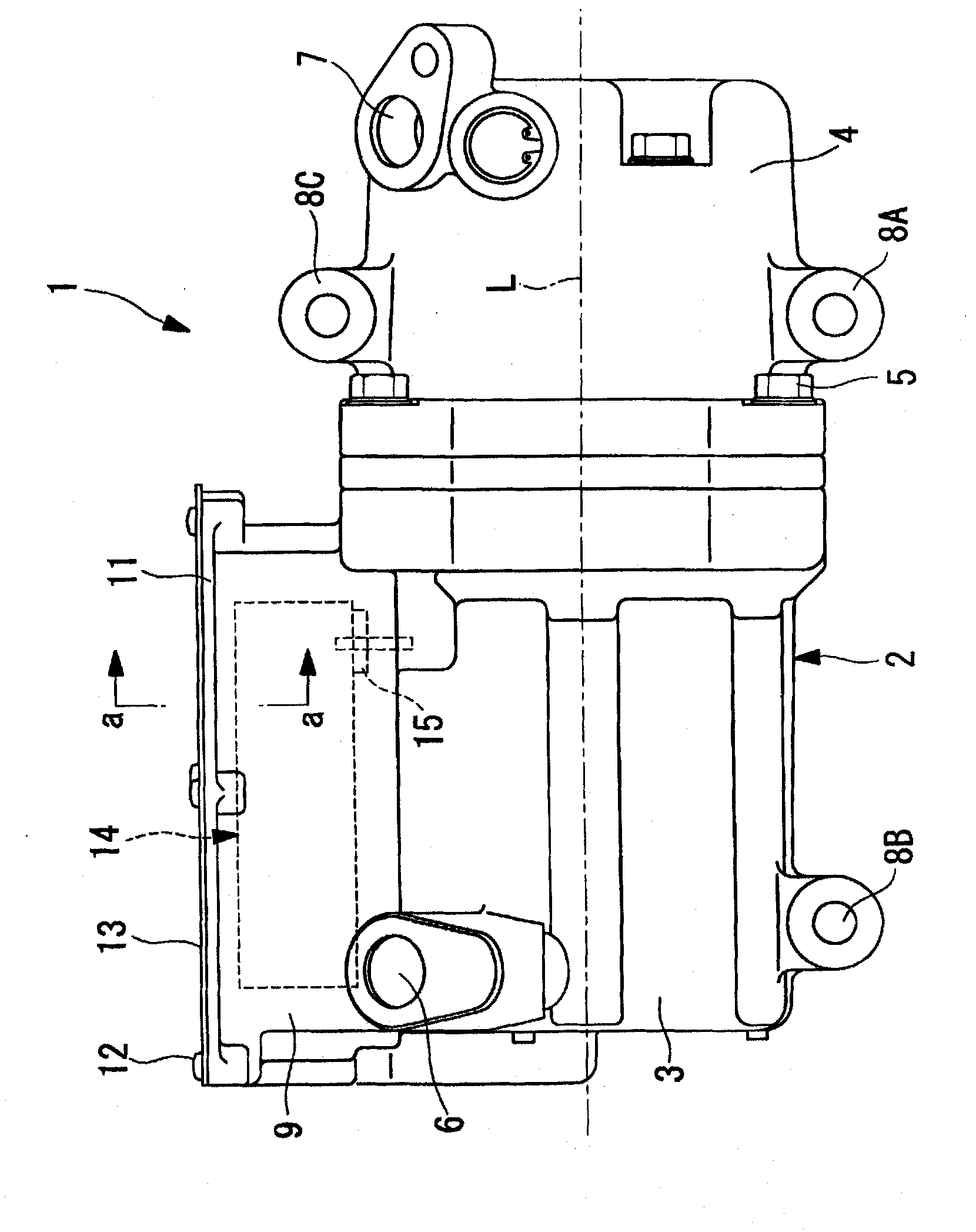
[0036] exist figure 1 shows a side view of the appearance of the inverter-integrated electric compressor related to the first embodiment of the present invention, and figure 2 means with figure 1 The equivalent graph of the a-a profile, in image 3 The middle side shows the end view of the opening side of the converter housing part. The inverter-integrated electric compressor 1 has a casing 2 constituting its outer casing. The housing 2 is constructed by integrally fastening a motor housing 3 and a compressor housing 4 by using bolts 5. The motor housing 3 accommodates a motor not shown in the figure; the compressor housing 4, It accommodates a compression mechanism (not shown). The motor housing 3 and the compressor housing 4 are each made of die-cast aluminum.

[0037] The motor and the compression mechanism built in the casing 2 are connected via a motor shaft, and the compression mechanism is driven by the rotation of the motor. At one end of the motor housing 3 ( ...

no. 2 example

[0053] Next, refer to the attached Figure 5 A second embodiment of the present invention will be described.

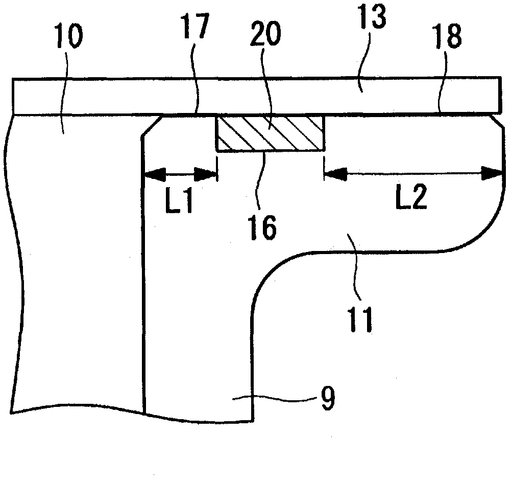
[0054] The difference between the present embodiment and the first embodiment is that a small gap D1 is formed between the joint surface 17 of the flange portion 11 and the cover body 13 . The other points are the same as those of the first embodiment, so explanations are omitted.

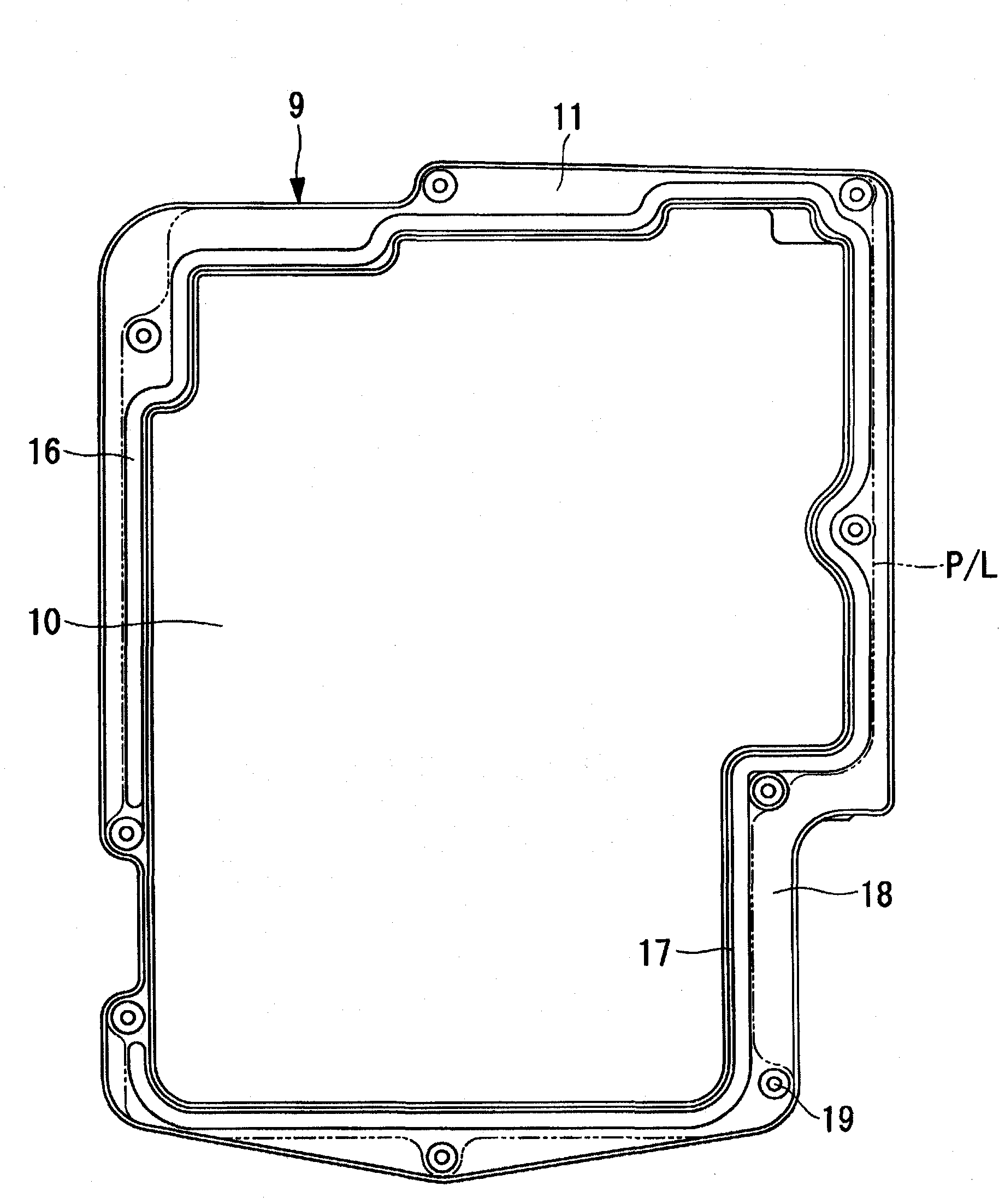
[0055] In this example, if Figure 5 As shown, on the flange part 11 of the converter housing part 9, the height of the joint surface 17 formed on the inner peripheral side of the groove 16 is lower than the height of the joint surface 18 formed on the outer peripheral side of the groove 16, so that A small gap D1 is formed between the surface 17 and the cover body 13 . In addition, it is sufficient that the minute gap D1 is about 0.1 mm. exist Figure 5 In , the size of the gap D1 is exaggeratedly enlarged.

[0056] As mentioned above, on the flange portion 11, the height of the joi...

no. 3 example

[0058] Next, refer to the attached Figure 6 A third embodiment of the present invention will be described.


PUM


Abstract

An electric compressor integral with an inverter, wherein waterproof properties of an inverter containing section are reliably enhanced by minimizing a variation in sealing ability. An electric compressor integral with an inverter, wherein an inverter containing section (9) is provided on the outer periphery of a housing, an inverter device for supplying driving electric power to an electric motor is mounted in the inverter containing section (9), and an opening (10) of the inverter containing section (9) is hermetically sealed by a lid body (13). A groove (16) for placing therein a liquid seal agent (20) is provided in a flange (11) surrounding an opening (10) of the inverter containing section (9), and the joint between the flange (11) and the lid body (13) is hermetically sealed by allowing the liquid seal agent (20) placed in the groove (16) to cure. The electric compressor satisfies the relationship of L1 < L2, where L1 is the width of a joint surface (17) formed on the inner peripheral side of the groove (16) in the flange (11) and L2 is the width of a joint surface (18) formed on the outer peripheral side of the groove (16).

Description

technical field [0001] The present invention relates to an inverter-integrated electric compressor suitable for use in a vehicle air conditioner and in which the inverter device is integrally mounted. Background technique [0002] In recent years, the popularization and development of hybrid vehicles, electric vehicles, fuel cell vehicles, etc. are actively underway. In vehicle air conditioners mounted on these automobiles, an inverter-integrated electric compressor with a built-in motor is used instead of an open compressor driven by power from an engine. Inverter-integrated electric compressors are equipped with an inverter housing part on the outer periphery of the casing in which the motor and compression mechanism are built. Inside the converter housing part are assembled: the DC power supplied by the high-voltage power supply is converted into three-phase AC power and passed through the glass. A sealed terminal is supplied to an inverter device of a motor (for example...

Claims


Application Information

Patent Timeline
IPC IPC(8): F04B39/00F04C29/00
CPCF01C21/10F04B39/121F04B2203/0204F04C2240/808F04B35/04F16J15/14
Inventor 铃木学余语一朗大崎智康
Owner MITSUBISHI HEAVY IND LTD
Why Eureka
Try Eureka