Grid deformation method based on local rigidity

A mesh deformation and partial technology, applied in image data processing, instruments, etc., can solve problems such as slow deformation and distortion

Inactive Publication Date: 2011-05-11
NORTHWEST UNIV(CN)
View PDF2 Cites 22 Cited by
  • Summary
  • Abstract
  • Description
  • Claims
  • Application Information

AI Technical Summary

Problems solved by technology

Linear methods lead to locally non-rigid results, while deforming the 3D model as a whole results in slow deformations and local distortions

Method used


Image

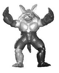
  • Grid deformation method based on local rigidity
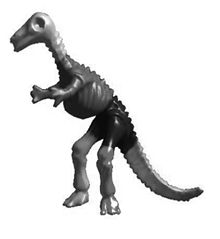
  • Grid deformation method based on local rigidity
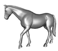
  • Grid deformation method based on local rigidity

Examples


specific Embodiment

[0038] This embodiment is specifically carried out through the following steps:

[0039] Step 1: Use the grid segmentation method of global point feature to automatically or manually segment the read grid model:

[0040] (1) For each vertex v of the mesh model i GPS (Global Point Signature), that is, the global point feature is expressed as:

[0041] GPS ( v i ) = ( 1 λ 1 H i 1 , 1 λ 2 H i 2 , . . . , 1 λ k H i k , . . . )

[0042] Where λ k Is the characteristic value, Corresponds to the vertex v i Eigenvector H k value

[0043] (2) At the vertex v of the mesh model i Select K vertices as the initial class center m j ;

[0044] (3) Traverse all vertices v of the mesh model i , Assign it to the nearest class center m j ;

[0045] (4) Calculate the new class center m j , And the error value E;

[0046] (5) Execute (3) and (4) in this step in a loop until the absolute value of the diffe...


PUM


Abstract

The invention belongs to the field of digital and geometric processing in computer graphics, and in particular to a 3D grid model deformation editing method based on the local rigidity principle. The invention aims at providing a deformation editing method having a fine deformation effect and a satisfactory deformation interaction speed, which is used for model reuse. The method uses grid segmentation and manifold Laplace transform to increase the local rigidity-based deformation editing speed and comprises the following steps: segmenting a 3D model into multiple parts by the grid segmentation, deforming parts which need to be deformed, and splicing the multiple parts, thereby greatly increasing the deformation speed and simultaneously avoiding distortion conditions at the joints. Besides, the manifold Laplace transform can greatly reduce the dimension of linear system of equations of corresponding deformation, thereby achieving higher result controllability.

Description

Technical field [0001] The invention belongs to the field of computer graphics digital geometry processing, and particularly relates to a method for deforming and editing a three-dimensional mesh model based on the principle of local rigidity. Through efficient model deformation editing technology to achieve the purpose of model reuse, it has important application value in geometric modeling, computer animation, film and television games, virtual reality and other computer graphics applications. Background technique [0002] With the in-depth application of computer graphics technology in computer animation, film and television games and other fields, the application of 3D models has become more and more extensive, relying on the advancement of information acquisition technologies such as laser scanning and digital photography to quickly obtain 3D geometric data from the real world It has become very easy. Users can reconstruct complex geometric models from the acquired high-prec...

Claims


Application Information

Patent Timeline
Patent Type & Authority Applications(China)
IPC IPC(8): G06T19/00
Inventor 耿国华周明全李欧洲李康杜卓明
Owner NORTHWEST UNIV(CN)
Why Eureka
Try Eureka