
Wax deposition experimental device

An experimental device, wax deposition technology, applied in measurement devices, particle and sedimentation analysis, particle size analysis, etc., can solve problems affecting pipeline pressure drop, pipeline transportation capacity reduction, transportation pressure increase, etc., to achieve advanced experimental equipment, suitable for Wide range, accurate measurement results

Inactive Publication Date: 2011-05-18
CHINA UNIV OF PETROLEUM (BEIJING)
View PDF2 Cites 24 Cited by
  • Summary
  • Abstract
  • Description
  • Claims
  • Application Information

AI Technical Summary

Problems solved by technology

[0003] The above-mentioned wax deposition process has brought the following series of problems to the pipeline transportation of waxy crude oil: the effective inner diameter of the pipeline is reduced, the transmission pressure is increased, the pipeline transmission capacity is reduced, the frequency of pigging is increased, and even wax plugging accidents are caused; and the pipeline transportation Waxy crude oil is prone to changes in flow pattern and flow state when the outbound oil temperature is low and the flow rate is low, which will affect the pressure drop of the pipeline and increase the operating cost of the pipeline
[0004] At present, the loop wax deposition experiments are carried out under normal pressure or low pressure environment. Even if the loop design can carry out split-type multiphase flow wax deposition experiments, the experimental gas used is mainly air. , but there are certain limitations in the study of other experimental gaseous media

Method used


Image

  • Wax deposition experimental device
  • Wax deposition experimental device
  • Wax deposition experimental device

Examples


Embodiment Construction

[0021] In order to have a clearer understanding of the technical features, purposes and effects of the present invention, the specific implementation manners of the present invention will now be described with reference to the accompanying drawings.

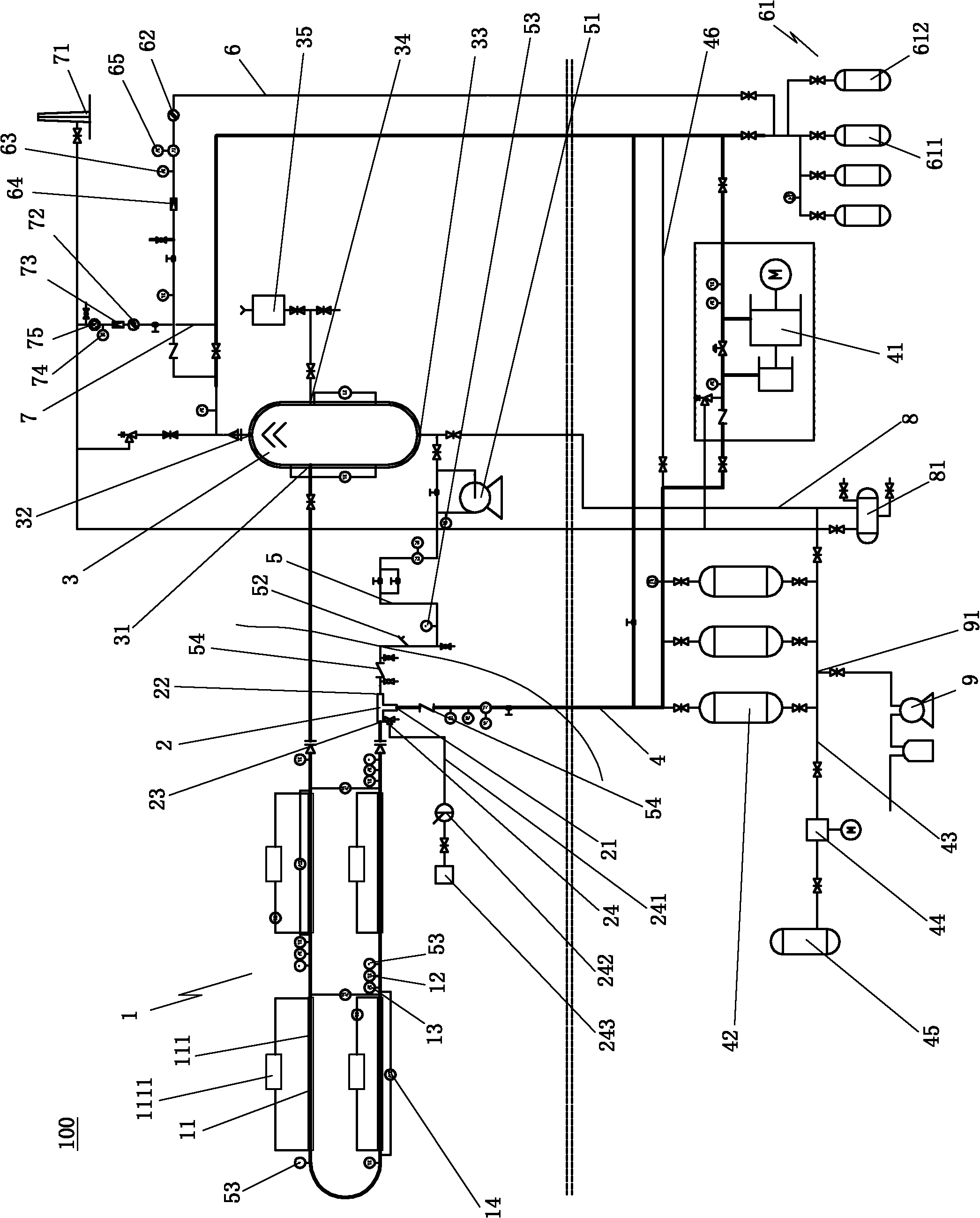
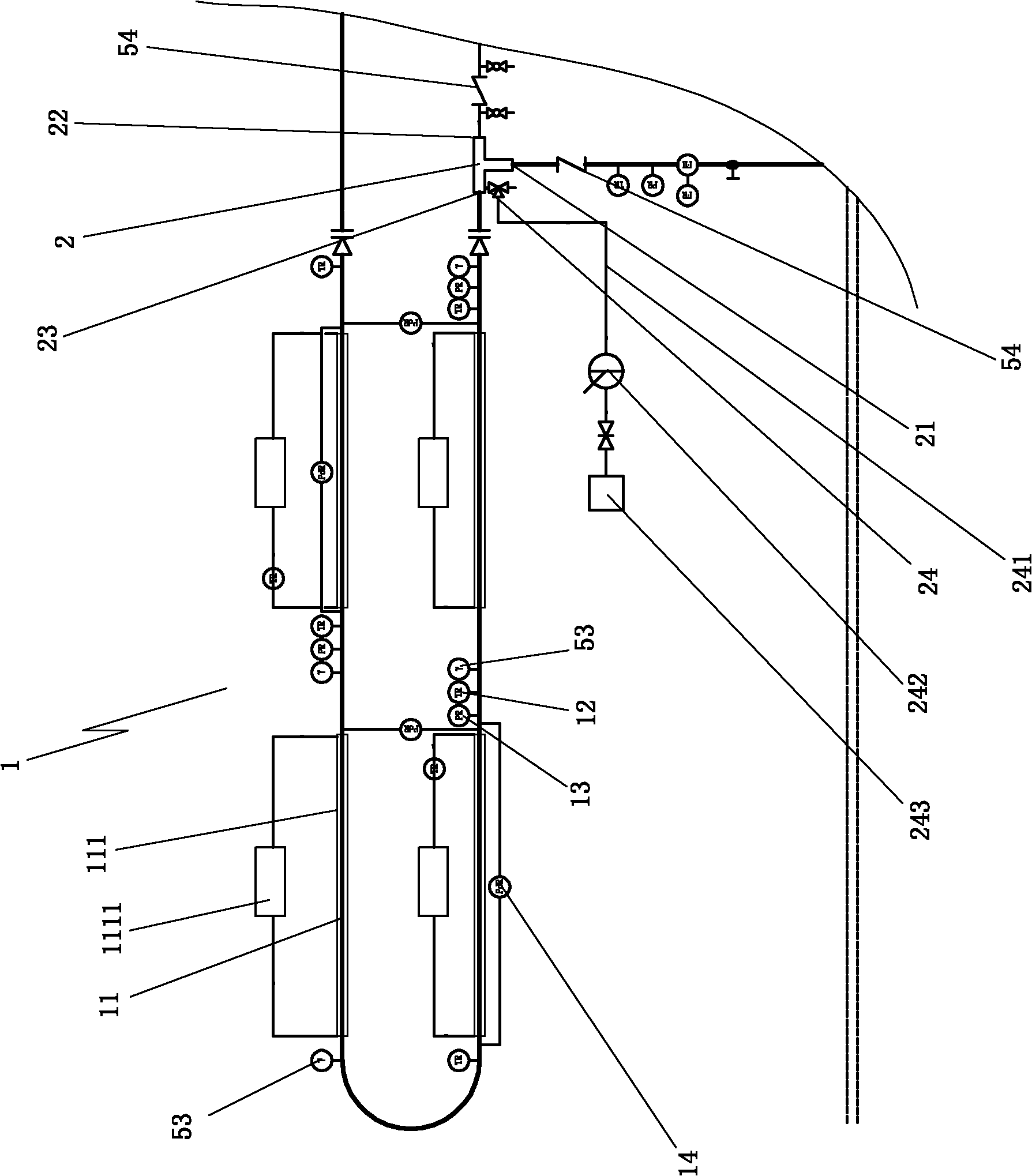
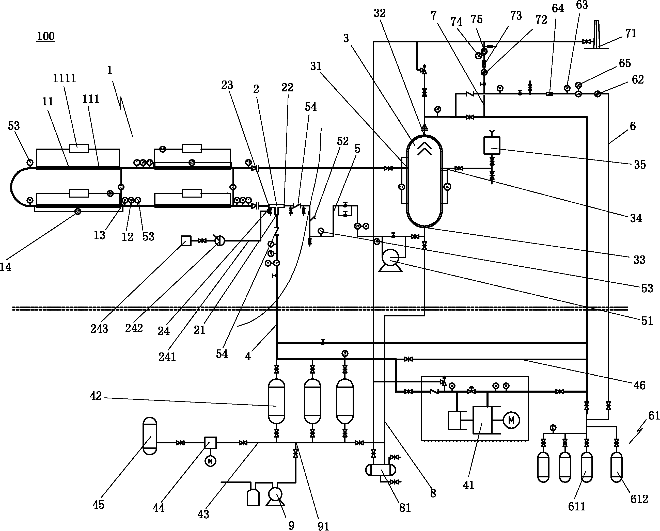
[0022] Such as figure 1 , figure 2 As shown, the present invention proposes a wax deposition experimental device 100, the experimental device 100 includes an experimental pipeline 1, one end of the experimental pipeline 1 is connected to the outlet 23 of a gas-liquid mixer 2, the other end of the experimental pipeline 1 Be communicated with the liquid return port 31 of a gas-liquid separator 3; the air inlet 21 of the gas-liquid mixer 2 is communicated with the exhaust port 32 of the gas-liquid separator 3 through a circulation compressor 41; the gas-liquid mixer The liquid inlet 22 of 2 is communicated with the liquid outlet 33 of gas-liquid separator 3 through a multiphase pump 51, thus, this experimental pipeline 1 forms a c...


PUM


Abstract

The invention relates to a wax deposition experimental device. The experimental device comprises an experimental pipeline, wherein on end of the experimental pipeline is communicated to an outlet of a gas and liquid mixer; the other end of the experimental pipeline is communicated to a liquid return port of the gas and liquid separator; a gas inlet of the gas and liquid mixer is communicated to an exhaust port of the gas and liquid separator through a circulation compressor; a liquid inlet of the gas and liquid mixer is communicated to a liquid discharging port of the gas and liquid separator through a multiphase pump; a pipeline between the multiphase pump and the liquid inlet of the gas and liquid mixer is also provided with a laser particle size analyzer and an on-line gamma phase fraction instrument; the experimental pipeline is provided with a plurality of measuring sections at intervals; each measuring section can be detachably serially connected to the experimental pipe, the outer sides of the pipeline of all measuring sections are respectively provided with a temperature control water bath jacket; and the inlet end of each measuring section of the pipeline is respectively provided with one on-line gamma phase fraction instrument. The experimental device has the characteristics of reasonable structure, ingenious design, advanced experimental equipment, wide application range, accurate measurement and the like and can save the experimental cost and reduce emission of harmful gas.

Description

technical field [0001] The invention relates to a pipeline waxing experimental device in crude oil transportation, in particular to a device suitable for multiphase flow, single-phase flow wax deposition research and multiphase flow flow under high-pressure, flammable and explosive hydrocarbon experimental gas environments. Experimental setup for wax deposition measurements. Background technique [0002] Waxy crude oil is a complex mixed system, which is mainly composed of wax, gum, aromatic hydrocarbon, asphalt and light hydrocarbon components. When the temperature is high, the wax component in the crude oil is in a dissolved state, and the crude oil exhibits Newtonian fluid rheological properties; as the temperature decreases, the wax component gradually crystallizes and precipitates, and the viscosity of the crude oil increases accordingly, and presents a non-Newtonian rheological property. properties of the fluid. When the amount of wax crystals precipitated reaches 2%...

Claims


Application Information

Patent Timeline
IPC IPC(8): G01N25/12G01N15/02
Inventor 宫敬李文庆于达吴海浩
Owner CHINA UNIV OF PETROLEUM (BEIJING)
Learn More