Oscilloscope with high-frequency path and low-frequency path separation circuit

A technology that separates circuits, high frequency and low frequency, and is applied in the direction of instruments, measuring electrical variables, digital variables/waveform display, etc. It can solve the problems of low DC accuracy of JFET circuits, small signal input offset range, and insufficient output drive capability. Achieve the effect of increasing the maximum working voltage, wide range of signal input offset, and less susceptible to interference

Active Publication Date: 2011-05-18
RIGOL
View PDF5 Cites 25 Cited by
  • Summary
  • Abstract
  • Description
  • Claims
  • Application Information

AI Technical Summary

Problems solved by technology

[0007] 1), DC precision is not high
Since the input pole is completely followed by the JFET circuit, the DC accuracy of the JFET circuit is not high
[0008] 2), input withstand voltage is low
[0009] 3), the input capacitance is large
[0010] 4), low bandwidth
Large input capacitance, resulting in low input bandwidth
[0011]

Method used


Image

  • Oscilloscope with high-frequency path and low-frequency path separation circuit
  • Oscilloscope with high-frequency path and low-frequency path separation circuit
  • Oscilloscope with high-frequency path and low-frequency path separation circuit

Examples


Embodiment 1

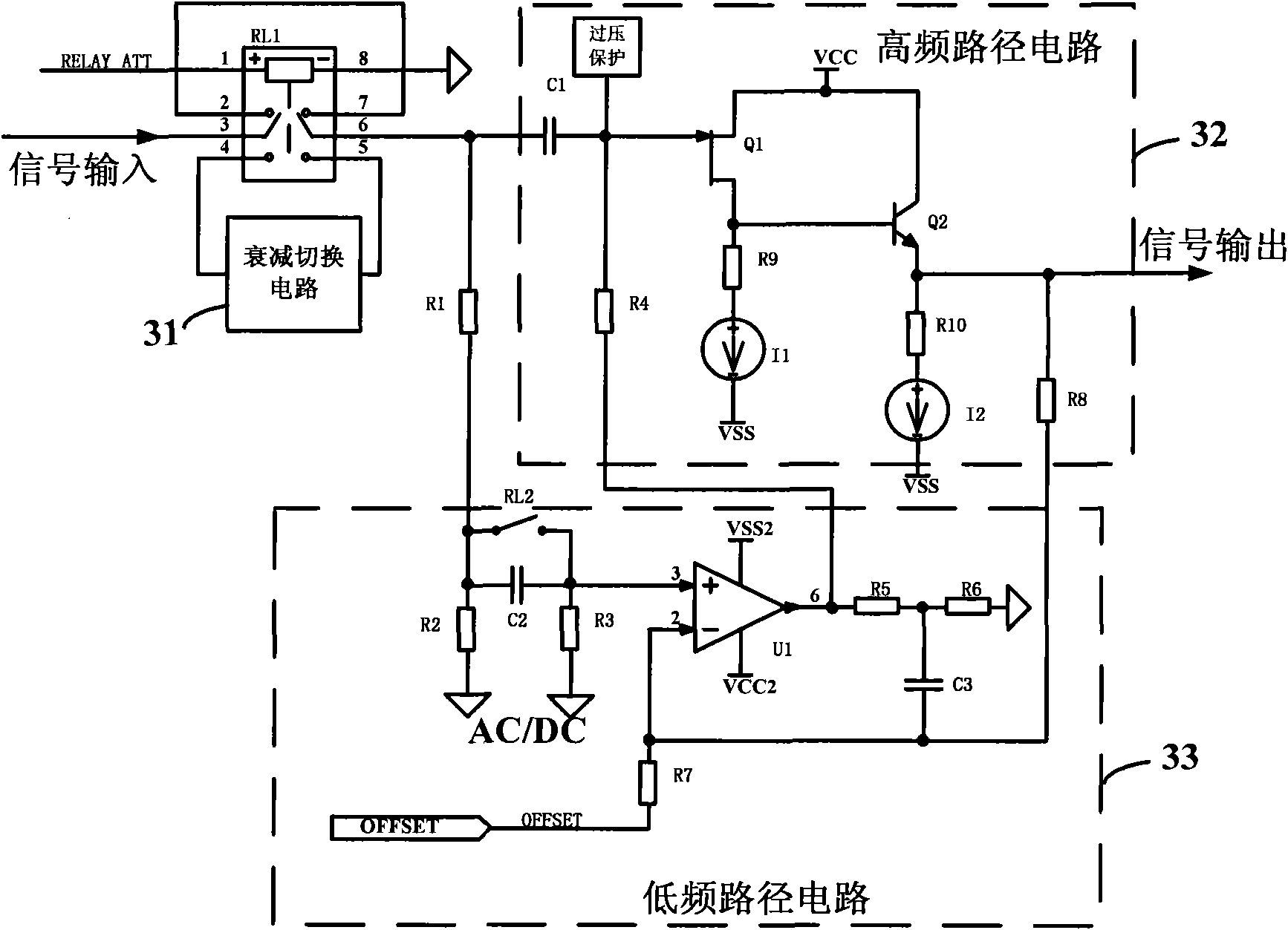
[0088] Such as Figure 13 as shown, Figure 13 It is an oscilloscope provided with a high-frequency and low-frequency path separation circuit according to the first embodiment of the present invention. In this embodiment 1, 2SK508-K51 is selected for the high-frequency path Q1, and MMBTH10LT1 is selected for Q2, so as to realize a high-bandwidth high-frequency path. For the low-frequency path, select the high-precision op amp AD8510 with input protection inside. Select resistor R1=R8=806kΩ, R2=R3=392kΩ, R7=208.4kΩ, R5=12kΩ, R6=3kΩ. Satisfy R1 / (R2||R3)=R8 / R7=R5 / R6, so that the gains of high and low frequencies are consistent. R4 chooses a large resistance of 4.7MΩ

Embodiment 2

[0090] Such as Figure 14 as shown, Figure 14 It is an oscilloscope provided with a high-frequency and low-frequency path separation circuit according to the second embodiment of the present invention. In the second embodiment, MMBF5486 is selected for the high-frequency path Q1, and BFQ67 is selected for Q2 to realize a high-bandwidth high-frequency path. For the low-frequency path, the high-precision operational amplifier LMV842 is selected. Select resistor R1=R5=678kΩ, R2=R6=322kΩ, R7=237kΩ, R8=500kΩ. Satisfy R1 / R2=R8 / R7=R5 / R6, so that the gains of high and low frequencies are consistent. R4 selects a large resistance 1MΩ


PUM


Abstract

The invention discloses an oscilloscope with a high-frequency path and low-frequency path separation circuit, comprising a high-frequency path and low-frequency path separation circuit. The high-frequency path and low-frequency path separation circuit comprises an attenuation switch circuit, a high-frequency path circuit and a low-frequency path circuit, wherein the input signal of the oscilloscope enters the attenuation switch circuit and is switched by a double-pole-double-throw switch in the attenuation switch circuit; then the input signal enters the high-frequency path circuit and the low-frequency path circuit; the input signal of the oscilloscope is output respectively from the high-frequency path circuit and the low-frequency path, the ratio of a high-frequency output signal and a high-frequency input signal is 1:1, the ratio of a low-frequency output signal and a low-frequency input signal is 1:1, i.e. the ratio of signal input and signal output is 1:1 follow; and thus, the separation process of high-frequency components and low-frequency components is finished. The invention realizes an oscilloscope input circuit with high input resistance, low input capacitance, high DC(Direct Current) precision, high input pressurization, big bandwidth, low noise, large signal input shift range and good frequency response flatness.

Description

technical field [0001] The invention relates to an input analog circuit of an oscilloscope or other measuring instruments, in particular to an oscilloscope with a high-frequency and low-frequency path separation circuit. Background technique [0002] The input analog circuit of an oscilloscope or other measuring instruments determines key indicators such as its bandwidth. The measuring instrument will inevitably have an impact on the circuit under test. To minimize the impact, a high input resistance and a low input capacitance are required. , these two indicators are one of the important indicators of oscilloscope or measuring instrument. In addition to the functions of high input impedance and low input capacitance, the input analog circuit of the oscilloscope also completes functions such as AC coupling, DC coupling, large input bias voltage range, high input voltage, high DC measurement accuracy, high bandwidth, and low noise. These are the key indicators of the oscillo...

Claims


Application Information

Patent Timeline
IPC IPC(8): G01R13/00
Inventor 王悦王铁军李维森
Owner RIGOL
Why Eureka
Try Eureka