
Wall with tie steel mesh structure

A tie-type, steel mesh technology, applied in the direction of structural elements, walls, building components, etc., can solve the problems of heavy dependence on electric tools, waste of block materials, inconvenience, etc., to simplify the node joint process, reduce material consumption, reduce cost effect

Active Publication Date: 2013-07-24
谢英俊
View PDF1 Cites 2 Cited by
  • Summary
  • Abstract
  • Description
  • Claims
  • Application Information

AI Technical Summary

Problems solved by technology

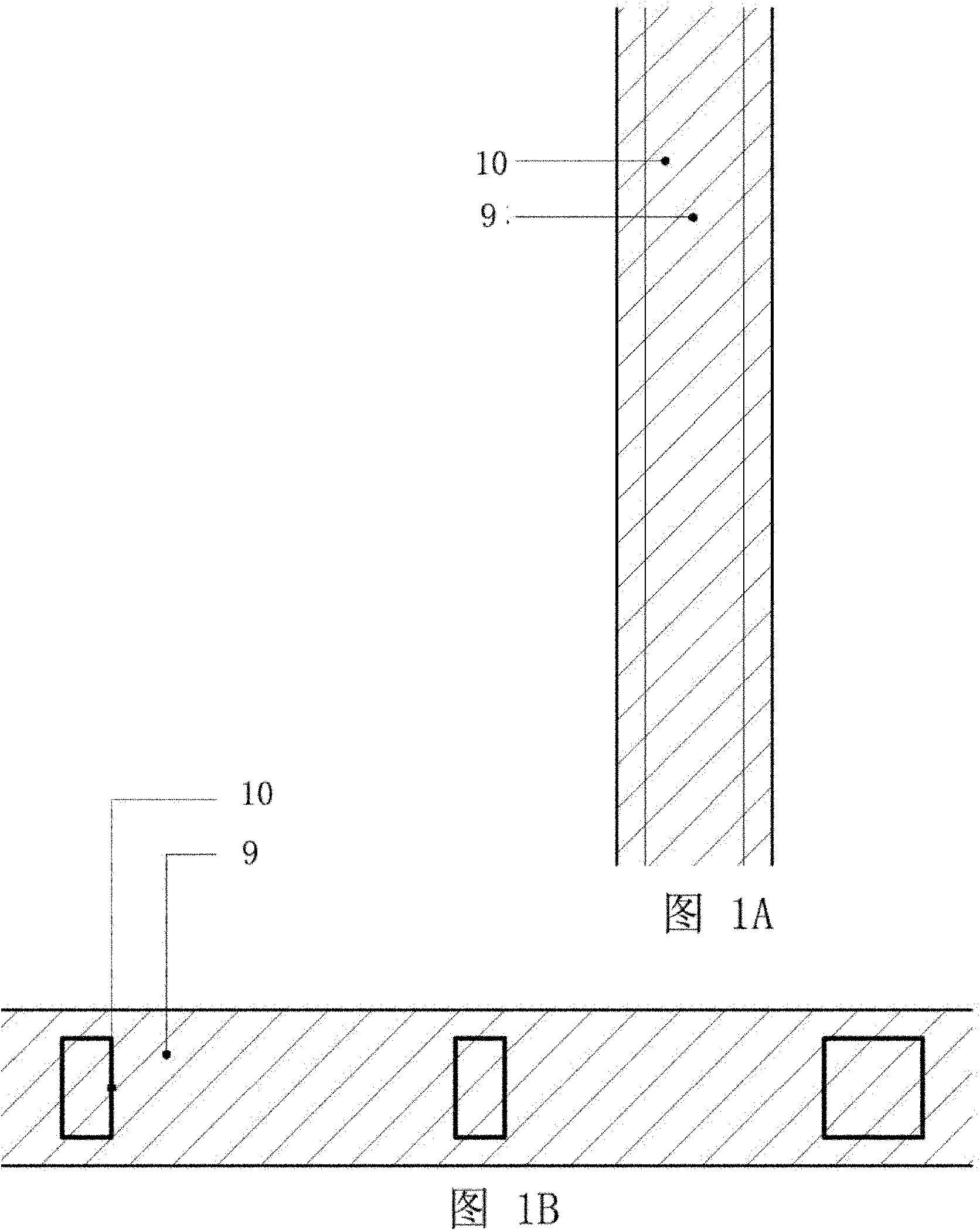
[0006] This kind of wall has the following problems: the block wall has poor flexibility in the selection and use of wall materials, the general block preparation site is separated from the building construction site, and sometimes requires a large transportation distance. Construction relies heavily on skilled workers, and at the same time, the stressed members 10 (columns and diagonal braces) of cold-formed thin-walled steel structure houses or wooden structures are too dense. The gap between components has a great impact on the construction of block masonry, and the waste of block materials is serious
[0012] (1) A large amount of keel material (steel or wood) is consumed, which increases the cost of the wall
[0013] (2) The thickness of the wall is limited by the width of the keel, and the cost of adjusting the specification of the keel is high, so the flexibility of wall size adjustment is poor
[0014] (3) During the construction process, there is a greater dependence on electric tools and higher requirements on the construction environment
[0015] This shows that above-mentioned existing body of wall obviously still has inconvenience and defect in structure and use, and urgently needs to be further improved

Method used


Image

  • Wall with tie steel mesh structure
  • Wall with tie steel mesh structure
  • Wall with tie steel mesh structure

Examples


Embodiment 1

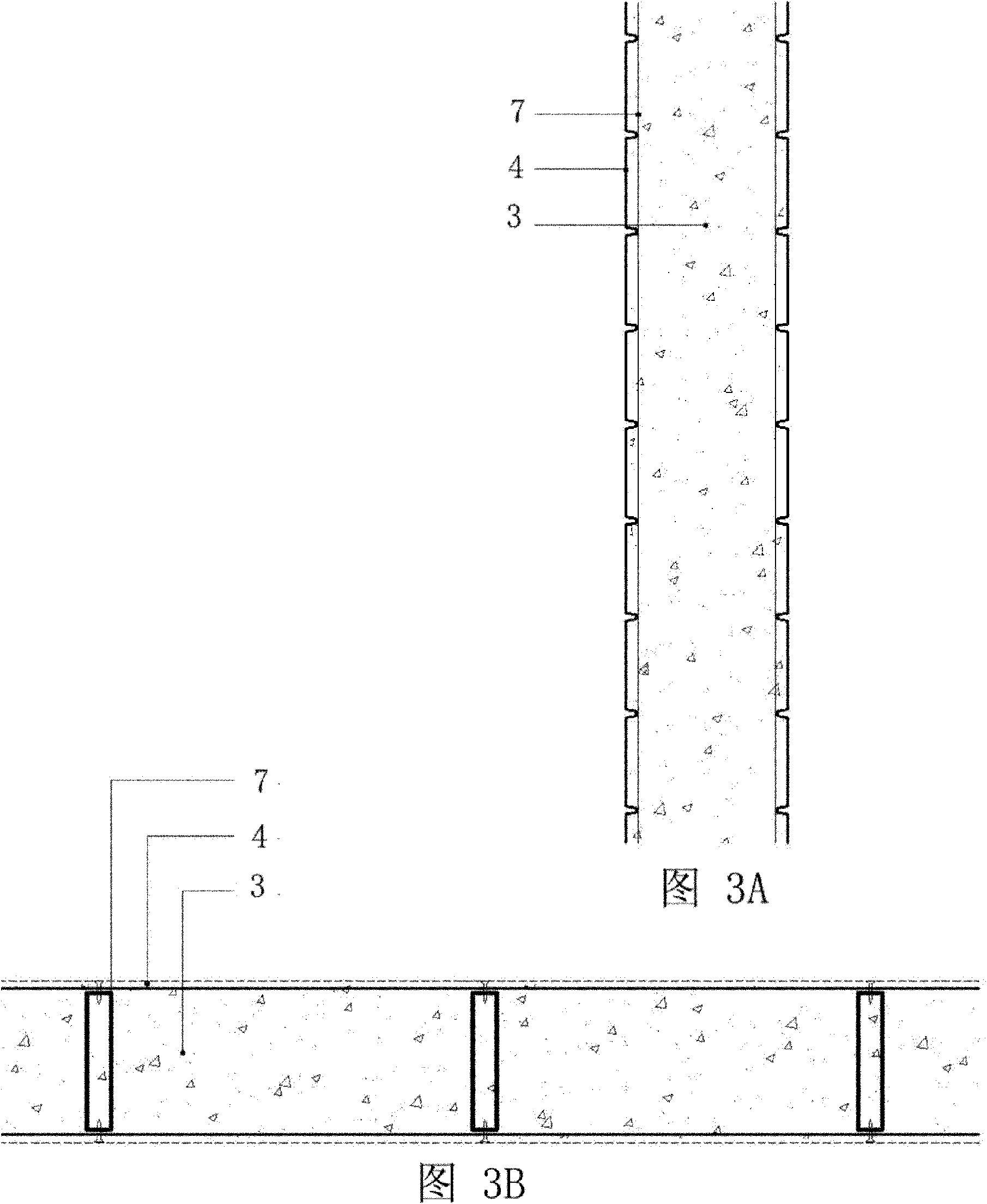
[0060] Figure 4A , 4B and Figure 5 Shown is a preferred embodiment of the present invention, and in this embodiment, the body of wall that is provided with tie-type steel mesh structure in China is made of transverse tension structure member 1, longitudinal positioning support member 2, filling layer 3 and have The rib expansion net 4 is composed of; the filling layer 3 is filled between the rib expansion net 4 on both sides, the rib expansion net 4 on both sides is fixedly connected with the longitudinal positioning support member 2, and the transverse tension member 1 passes through the filling layer 3 , its two ends are respectively fixed on the longitudinal positioning support member 2 that is fixedly connected with the rib expansion net 4 on both sides; the horizontal tension structure 1, the longitudinal positioning support member 2, the filling layer 3 and the rib expansion net 4 are integrated A wall with a tie-type steel mesh structure is formed.

[0061] In this...

Embodiment 2

[0066] Figure 7A and 7B Shown is the structural representation of the wall body that this embodiment is provided with pull-type steel mesh structure, wherein Figure 7A is the longitudinal section of the wall shown, Figure 7B is the cross section of the wall shown. The wall body provided with the tie-type steel mesh structure in this embodiment is composed of a transverse tension structure 1, a longitudinal positioning support member 2, a filling layer 3, a ribbed expansion net 4 and a painting layer 6, wherein the filling layer 3 is filled in Between the ribbed expansion nets 4 on both sides, the ribbed expansion nets 4 on both sides are fixedly connected to the longitudinal positioning support members 2, and the transverse tension member 1 passes through the filling layer 3, and its two ends are respectively fixed on the ribbed nets on both sides. The expansion mesh 4 is fixedly connected to the longitudinal positioning support member 2 . In order to make the wall with...

Embodiment 3

[0068] Figure 8A and 8B Shown is the structural representation of the wall body that this embodiment is provided with pull-type steel mesh structure, wherein Figure 8A is the longitudinal section of the wall shown, Figure 8B is the cross section of the wall shown. In this embodiment, on the basis of the embodiment 2, a waterproof and thermal insulation partition layer 5 is further arranged on the inner side of the ribbed expansion net 4 on the outer side of the outer wall. The waterproof and thermal insulation partition layer 5 has the function of waterproof and thermal insulation, and it is composed of a waterproof thermal insulation layer made of aluminum foil, linoleum or foam material.

[0069] The stucco layer and partition layer mentioned in the above embodiments can be designed according to the geographical factors and material factors of the construction site, and the design and combination of these components do not constitute a limitation of the present inventi...


PUM


Abstract

The invention relates to a wall with a tie steel mesh structure. The wall comprises steel meshes, a transverse tie member, a longitudinal positioning supporting member and a filling layer, wherein the filling layer is filled between the steel meshes on the two sides; the steel meshes on the two sides are fixedly connected with the longitudinal positioning supporting member; the transverse tie member passes through the filling layer, and the two ends of the transverse tie member are respectively fixed on the longitudinal positioning supporting member which is fixedly connected with the steel meshes on the two sides; and the steel meshes, the transverse tie member, the longitudinal positioning supporting member and the filling layer are integrated into the wall with the tie steel mesh structure. The invention has the advantages that: the wall with the tie steel mesh structure is safer and more environmental-friendly, has higher thermal insulation property and water resistance, is convenient to construct on site, and saves materials and cost more.

Description

technical field [0001] The invention relates to a wall used in the field of construction, in particular to a wall with a tie-type wall that is suitable for cold-formed thin-walled steel structure houses and wooden structure houses, and used for reinforcement of existing blocks or filled walls. Wall of steel mesh structure. Background technique [0002] Research and development of safe, energy-saving, environmentally friendly and cost-saving buildings is a trend in the development of the construction industry, and the development of walls with material savings, good performance, and low cost is the key to achieving these goals. [0003] At present, the walls used in cold-formed thin-walled steel structure houses and wood structure houses are generally block walls, keel steel mesh-filled walls and keel seal plate-filled walls. In terms of the use of keels, the walls of cold-formed thin-walled steel structure houses usually use light steel keels, and the walls of wood-structur...

Claims


Application Information

Patent Timeline
Patent Type & Authority Patents(China)
IPC IPC(8): E04B2/00E04G23/02E04F13/02E04C5/04E04C5/06
Inventor 谢英俊
Owner 谢英俊
Learn More