Method for designing ultra wideband impedance matching network

A technology of impedance matching network and design method, which is applied in the direction of impedance network, multi-terminal pair network, electrical components, etc., can solve the problems of complex calculation process and inconvenient operation, and achieve the effect of simple matching process, good matching function and realization of matching function

Inactive Publication Date: 2011-05-25
CHONGQING UNIV OF POSTS & TELECOMM
View PDF2 Cites 45 Cited by
  • Summary
  • Abstract
  • Description
  • Claims
  • Application Information

AI Technical Summary

Problems solved by technology

Although this design method can better complete the impedance matching, the calculation process is complicated and not easy to operate.

Method used


Image

  • Method for designing ultra wideband impedance matching network
  • Method for designing ultra wideband impedance matching network
  • Method for designing ultra wideband impedance matching network

Examples


specific Embodiment approach

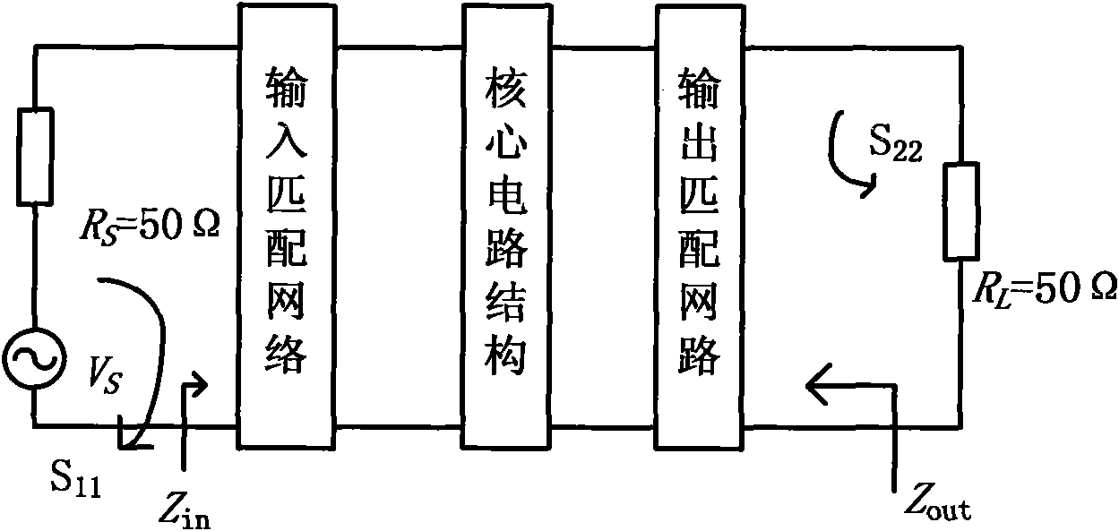
[0041] Step 1: Perform LNA S 11 and S 22 parametric simulation

[0042] Input the reflection coefficient S for the LNA structure that has completed the bias circuit design 11 and the output reflection coefficient S 22 The simulation of , get its corresponding Smith chart. Figure 9 Shown is the circuit structure of a basic common source low noise amplifier, and the bias circuit provides a suitable quiescent operating point for the amplifier.

[0043] Step 2: Design the input and output matching network of LNA

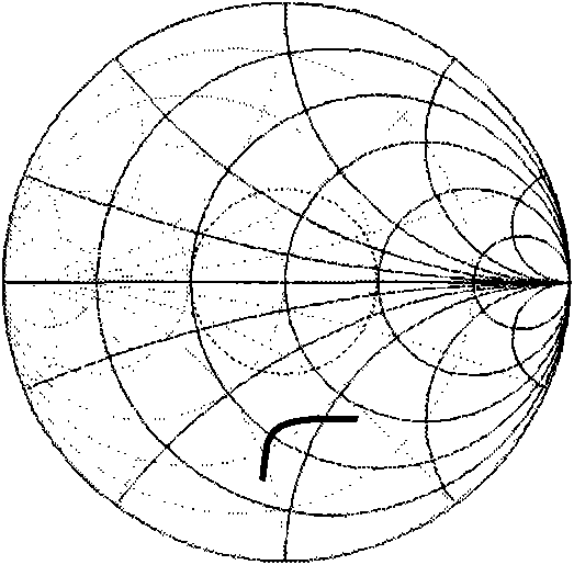
[0044] According to the Smith chart S 11 and S 22 The position and shape of the curve and the corresponding resistance R, reactance X, conductance G, and susceptance B of the high and low frequency end are in line with the phenomenon described above, that is, the reactance (or susceptance) corresponding to the high frequency end is smaller than that of the low frequency end. end. If a certain curve (S 11 or S 22 ) meets one of the two situations, then follow t...


PUM


Abstract

The invention discloses a method for designing a universal ultra wideband impedance matching network. A wideband matching network is added at the radio frequency input end or the radio frequency output end of a radio frequency circuit, and can be one of a T-type matching network, a Pi-type matching network and a hybrid matching network; elements in the matching network can be inductors or capacitors; the input reflection coefficient S11 or the output reflection coefficient S22 of the designed radio frequency circuit is shown in a Smith chart; an S11 curve or an S22 curve changes in the Smith chart by serially or parallelly connecting the inductors or the capacitors in the matching network; and the two curves finally completely fall into a -10dB impedance matching circle, so that the radio frequency circuit realizes impedance matching within an ultra wideband frequency band. An optimal ultra wideband impedance matching network can be conveniently designed by the method; and taking a low noise amplifier (LNA) as an example, for an optionally given LNA structure, an optimized matching network can be acquired by inserting one or more inductors or capacitors into an input and output matching network. In the process of designing the matching network, the positions of the reflection coefficient curves in the Smith chart are adjusted by adjusting the connecting mode and the sizes of the elements, and the reflection coefficient curves can move into reflection coefficient circles such as -10dB and the like in the range of an overall designing frequency band, so that the aim of accomplishing the good impedance matching in a wide frequency band range is fulfilled.

Description

technical field [0001] The invention relates to the field of radio frequency circuit design, in particular to a design method of a broadband matching network circuit in a radio frequency circuit. technical background [0002] With the development of wireless communication technology, a short-distance high-speed wireless access technology with the characteristics of high data transmission rate, strong anti-interference ability and low power consumption - ultra-wideband (UWB) technology has attracted widespread attention. It solves the major problems related to propagation that have plagued wireless technology for many years. It has the advantages of insensitivity to channel fading, low power spectral density of transmitted signals, low interception capability, low system complexity, and centimeter-level positioning accuracy. It is suitable for high-speed wireless access and military communication applications in dense multi-path places such as indoors. Compared with the trad...

Claims


Application Information

Patent Timeline
Patent Type & Authority Applications(China)
IPC IPC(8): H03H7/12
Inventor 王巍彭能罗元韩冰熊媛王颖王岳生冯世娟
Owner CHONGQING UNIV OF POSTS & TELECOMM
Why Eureka
Try Eureka