Firefighting remote monitoring communication system

A remote monitoring and communication system technology, applied in the field of fire remote monitoring and communication system, can solve problems such as lost data, no comprehensive sharing, failure to fire alarm, failure data statistical analysis, etc., to achieve balanced utilization of resources, high concurrency and stability, The effect of high concurrent processing capability

Inactive Publication Date: 2011-05-25
成都安吉斯信息技术有限公司
View PDF5 Cites 7 Cited by
  • Summary
  • Abstract
  • Description
  • Claims
  • Application Information

AI Technical Summary

Problems solved by technology

However, this kind of monitoring is scattered separately, and the monitoring room is set up in each unit, which makes it impossible for the fire department to supervise the work of the on-duty personnel, the alarm system is insufficiently maintained, and the lack of an effective maintenance management system and process makes it impossible to monitor Statistical analysis of fire alarm and fault data
[0003] At the same time, if it is necessary to monitor the fire protection facilities of each networked unit through a unified monitoring platform, and to be able to monitor the alarm information sent by each networked unit in real time, a special device is required to receive and analyze a large amount of alarm data, and if this device Without strong concurrency capabilities, data will be lost, and if the lost data happens to be a real fire alarm, serious consequences will occur
[0004] Another problem faced by the urban fire remote monitoring system is the need to establish a multi-level monitoring center, and the upper-level monitoring center needs to access the data of the lower-level monitoring center; however, the monitoring centers of most manufacturers are independent at present, and there is no data sharing or no full sharing

Method used


Image

  • Firefighting remote monitoring communication system
  • Firefighting remote monitoring communication system
  • Firefighting remote monitoring communication system

Examples


Embodiment 1

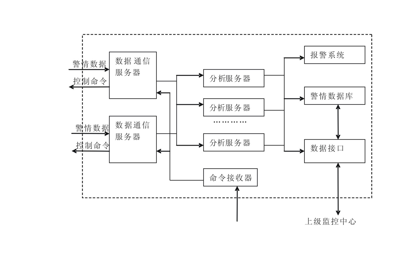
[0026] Embodiment 1: see figure 1 , figure 2 , image 3 , Figure 4 , the present invention is set in the monitoring center, which is divided into three-layer structure, including acquisition layer, analysis layer and processing layer, wherein the acquisition layer includes multiple data communication servers, only two are used in this embodiment, and the analysis layer includes multiple analysis Server, the processing layer includes an alarm system and an alarm database;

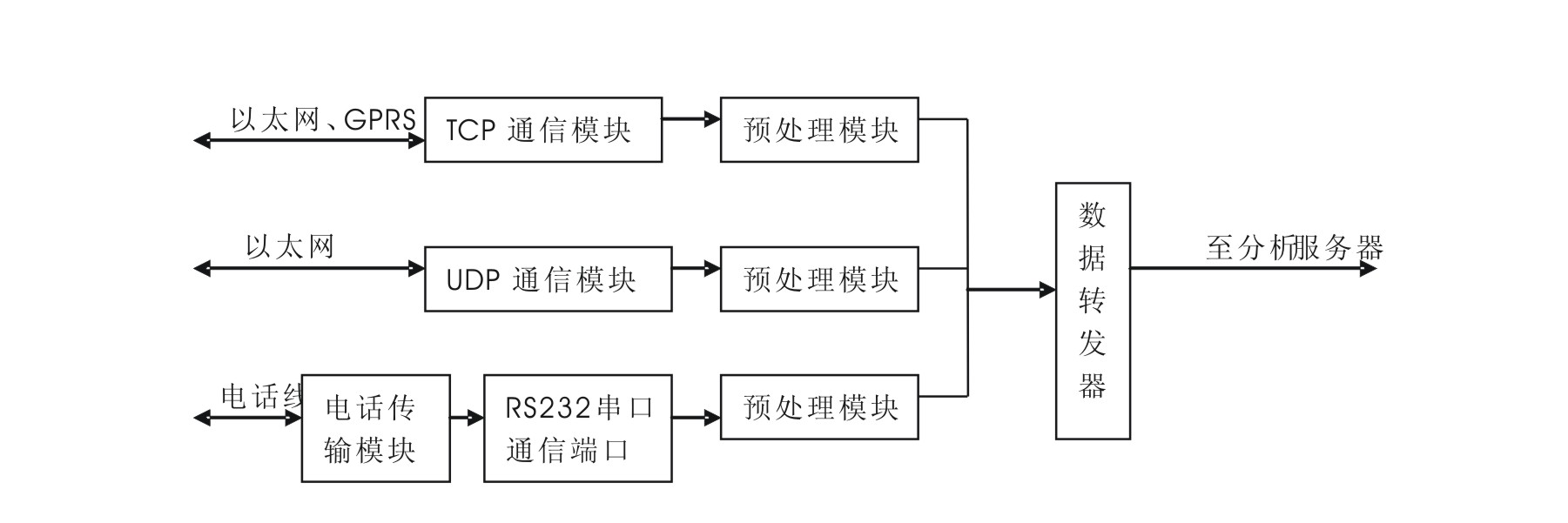
[0027] The data communication server collects the alarm data through Ethernet, GPRS, and telephone lines, and transmits the alarm data to the analysis server with the smallest number of tasks in the analysis layer through the load balancing algorithm, and receives and outputs user control commands. The specific implementation is as follows: The data communication server includes a TCP communication module for collecting Ethernet and GPRS information, a UDP communication module for collecting Ethernet in...


PUM


Abstract

The invention discloses a firefighting remote monitoring communication system, which comprises an acquisition layer, an analysis layer and a processing layer, wherein the acquisition layer comprises a plurality of sets of data communication servers; the analysis layer comprises a plurality of analysis servers; the processing layer comprises an alarming system; the data communication server acquires warning data, transmits the warning data to an analysis server with the smallest task number in the analysis layer through a load balancing algorithm, receives the control command of a user and outputs the control command of the user; and the analysis server analyzes the warning data, and outputs the analysis data to an alarming system, and the alarming system initiates an alarm. The firefighting remote monitoring communication system is arranged in a monitoring center, solves the problem that the conventional server has inadequate processing capacity and low concurrency and the problem that the multi-stage monitoring center lacks unified interface or even interface, has high concurrency handling capability and supports various data access modes. Monitoring centers can share data through a data interface and establish a superior and subordinate relationship, and a combination mode can be configured randomly.

Description

technical field [0001] The invention relates to a communication system, in particular to a fire remote monitoring communication system. Background technique [0002] In recent years, with the rapid development of information technology and network technology, the fire monitoring system in cities across the country has developed very rapidly, which effectively monitors the operation of the unit's internal fire protection facilities and achieves the purpose of timely detection of alarm conditions. However, this kind of monitoring is scattered separately, and the monitoring room is set up in each unit, which makes it impossible for the fire department to supervise the work of the on-duty personnel, the alarm system is insufficiently maintained, and the lack of an effective maintenance management system and process makes it impossible to monitor Statistical analysis of fire alarm and fault data. [0003] At the same time, if it is necessary to monitor the fire protection facili...

Claims


Application Information

Patent Timeline
Patent Type & Authority Applications(China)
IPC IPC(8): H04L29/08H04M11/04
Inventor 姜胜雷
Owner 成都安吉斯信息技术有限公司
Why Eureka
Try Eureka