Varnish filter

A filter and varnish technology, applied in chemical instruments and methods, dispersed particle separation, combined devices, etc., can solve the problems of poor filter treatment effect, poor water solubility of varnish, secondary pollution, etc. Small size, easy operation and high purification efficiency

Active Publication Date: 2011-06-01
GARDEN ENVIRONMENTAL PROTECTION
View PDF5 Cites 9 Cited by
  • Summary
  • Abstract
  • Description
  • Claims
  • Application Information

AI Technical Summary

Problems solved by technology

[0003] Varnish waste gas liquid oils are very easy to solidify, which brings great difficulty to treatment. At present, there are two main treatment methods, namely dry filtration and wet filtration. Dry filtration generally only uses non-woven filter materials Oil removal i

Method used


Image

  • Varnish filter
  • Varnish filter

Examples


Embodiment Construction

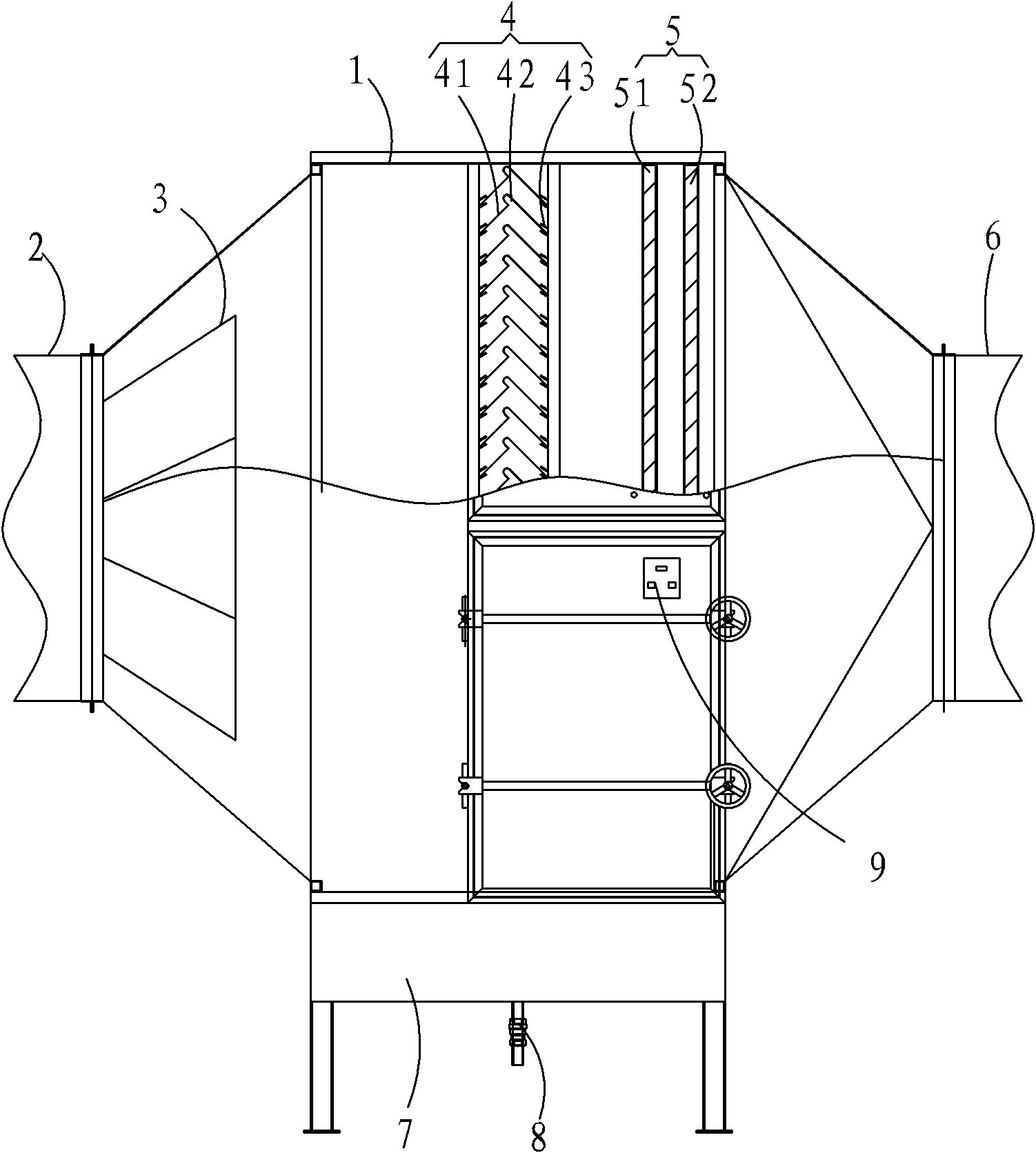
[0015] like figure 1 As shown in the figure, the varnish filter includes a housing 1. The housing 1 is sequentially provided with an air inlet 2, an air distribution device 3, a baffle blocking layer 4, a combined filter screen 5, and an air outlet 6 from the front end to the rear end. .

[0016] An oil collecting tank 7 is arranged at the inner bottom of the housing 1 , and an oil draining device 8 is arranged at the bottom of the oil collecting tank 7 .

[0017] The baffle-blocking layer 4 is composed of a plurality of equidistantly spaced inverted V-shaped baffles 41 , which are evenly arranged in the casing 1 from top to bottom. A protrusion 42 is provided on the top of the inverted V-shaped baffle 41 .

[0018] The combined filter screen 5 includes two layers, the filter screen layer 51 near the air outlet 1 is composed of multiple layers of wire meshes with different meshes, and the filter screen layer 52 near the air outlet 6 is composed of multiple layers of differen...


PUM


Abstract

The invention provides a varnish filter, which comprises a shell. An air inlet, an air distribution device, a baffle interception layer, a combined filtration net and an air outlet are arranged on the shell sequentially from the front end to the back end; a varnish collection tank is arranged at the bottom in the shell; a varnish discharge device is arranged at the bottom of the varnish collection tank; the baffle interception layer consists of a plurality of reverse V-shaped baffles which are separated at equal intervals and uniformly arranged in the shell from top to bottom; a protuberance is formed on the top of each of the reverse V-shaped baffles; the combined filtration net comprises two layers; the filtration net layer close to the air outlet consists of a plurality of layers of silk nets in different numbers, and the filtration net layer close to another air outlet is formed by combining a plurality of layers of fiber filter media of different densities. The varnish filter adopts multiple layers of intercepting and filtration devices to remove liquid oil dirt from varnish waste gas by grades; the intercepting and filtration devices adopt a drawable design, so the daily operation is convenient; the varnish filter occupies small space and is compact and rational in structure; the internal members can be exchanged easily without causing secondary pollution; and the purifying efficiency is high.

Description


Claims


Application Information

Patent Timeline
Owner GARDEN ENVIRONMENTAL PROTECTION
Why Eureka
Try Eureka