Variable stigmatic opening transmission device of engine

A transmission and engine technology, applied in the direction of engine components, combustion engines, machines/engines, etc., can solve problems such as corner wear, prevent the generation of beating sound, prevent beating sound, and prevent the axial width from expanding as much as possible Effect

Inactive Publication Date: 2011-06-01
HONDA MOTOR CO LTD
View PDF7 Cites 2 Cited by
  • Summary
  • Abstract
  • Description
  • Claims
  • Application Information

AI Technical Summary

Problems solved by technology

[0004] However, in the variable valve train disclosed in Patent Document 1, the cam abutting portion and the first cam side of the second cam are in the middle of moving the second cam to abut against the cam abutting portion of the cam follower. When the corner portion of the cam abuts against the second cam, the cam abuts when no axial driving force is applied to the second cam against the force acting on the second cam from the cam abutment portion to move the second cam toward the side away from the first cam. The amount of height difference between the second cam and the first cam may be lowered accordingly, so that the knocking sound caused by the impact contact between the abutting part of the cam and the first cam may be generated, and it may be on the side of the first cam of the second cam corner wear

Method used


Image

  • Variable stigmatic opening transmission device of engine
  • Variable stigmatic opening transmission device of engine
  • Variable stigmatic opening transmission device of engine

Examples


Embodiment 1

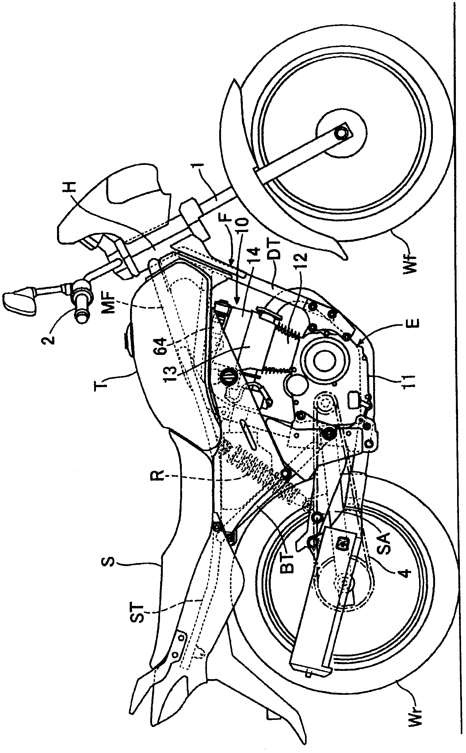
[0057] refer to Figure 1 to Figure 11 Embodiment 1 of the present invention is described, first, in figure 1 In this motorcycle, an engine E and a fuel tank T are mounted on a frame F of the motorcycle, and a front wheel Wf is supported at the front end of the frame F via a front fork 1. A vertically swingable swing arm SA that supports the rear wheel Wr is pivotally connected to an approximately central portion of the frame F, and a rear shock absorber R is provided between the swing arm SA and the frame F. In addition, the driving force of the engine E is transmitted to the rear wheel Wr via the chain transmission mechanism 4 .

[0058] The frame F includes: a head pipe H that supports the front fork 1 in a steerable manner; a down tube DT extending downward from the head pipe H and passing in front of the engine E; The main frame MF extending downward through the top and rear of the engine E; the seat tube ST whose front end is fixedly connected to the middle part of the...

Embodiment 2

[0103] refer to Figure 12 Embodiment 2 of the present invention will be described, and parts corresponding to those in Embodiment 1 will be shown with the same reference numerals and detailed description will be omitted.

[0104] An inclined surface 71B is formed on the side surface of the second exhaust-side cam 33 on the side of the first exhaust-side cam 31 (refer to Example 1), and the inclined surface 71B becomes larger as it goes toward the first exhaust-side cam 31 side. The camshaft 32 (refer to Example 1) is inclined so as to be inward in the radial direction. The inclined surface 71B is formed to have the same width over the entire circumference of the exhaust-side second cam 33 with reference to the outer peripheral surface of the exhaust-side second cam 33 , and the axis line of the camshaft 32 and the inclined surface 71B form the same width. The angle α is set to 5° to 45°, preferably 15° to 25°.

[0105] According to the second embodiment, the roller 56 (refe...


PUM


Abstract

The invention provides a variable stigmatic opening transmission device of an engine, wherein the engine with elasticity applied on the valve closing direction is in linkage connection with a cam driven member and the cam driven member is equipped with a cam abutting part for the abutting against a first and a second cams.According to the device, when the second cam moves toward the first cam, the impact of the cam abutting part to the first cam is avoided and the generation of the strike sound is also avoided.The first cam (31) is fixed to a camshaft (32).The second cam (33) can axially movebetween the motion position that the second cam can abut against the cam abutting part (56) and approach the first cam (31) and the non-motion position that the second cam cannot abut against the camabutting part (56) and go far from the first cam (31). The second cam (33) supported by the camshaft (32) is not capable of rotating relative to an axis.The first cam side of the mountain portion (33b) of the second cam is equipped with an inclined surface and the inclined surface inclines toward the internal of the radial direction of the camshaft.

Description

technical field [0001] The present invention relates to a variable valve transmission device for an engine, in which a cam follower provided with a cam abutting portion is arranged along the camshaft in interlocking and connected manner with an engine valve that is elastically biased in the valve closing direction by a valve spring. The fixed position of the axis, the first cam having the first base circle portion and the first cam mountain portion protruding outward from the first base circle portion can be fixed to the camshaft so as to be in contact with the cam contact portion, The second cam is axially movable between an operating position where it can come into contact with the cam abutting portion and is close to the first cam, and a non-operating position where it cannot abut against the cam abutting portion and is away from the first cam, and cannot move. The camshaft is relatively rotatably supported around the axis, wherein the second cam has a second base circle po...

Claims


Application Information

Patent Timeline
Patent Type & Authority Applications(China)
IPC IPC(8): F01L13/00F02M25/07
CPCY02T10/121Y02T10/12
Inventor 藤原一夫千叶一彦寺田保男山西辉英中沟大和
Owner HONDA MOTOR CO LTD
Why Eureka
Try Eureka