Dual-voltage driven and controlled buffer with atomized oil cavity loop

A drive control, dual-voltage technology, applied in shock absorbers, shock absorbers, liquid shock absorbers, etc., can solve the problems of affecting the thermal diffusion rate, the two cavities of the buffer should not be too large, and affecting the buffer efficiency, etc., to avoid The effect of oil return, speeding up thermal diffusion rate and speeding up response speed

Inactive Publication Date: 2011-06-01
NANJING UNIV OF AERONAUTICS & ASTRONAUTICS
View PDF6 Cites 10 Cited by
  • Summary
  • Abstract
  • Description
  • Claims
  • Application Information

AI Technical Summary

Problems solved by technology

However, due to space constraints, the two cavities of the buffer should not be too large, and the oil will be heated

Method used


Image

  • Dual-voltage driven and controlled buffer with atomized oil cavity loop
  • Dual-voltage driven and controlled buffer with atomized oil cavity loop
  • Dual-voltage driven and controlled buffer with atomized oil cavity loop

Examples


Embodiment Construction

[0031] Below in conjunction with accompanying drawing, the present invention is described in further detail;

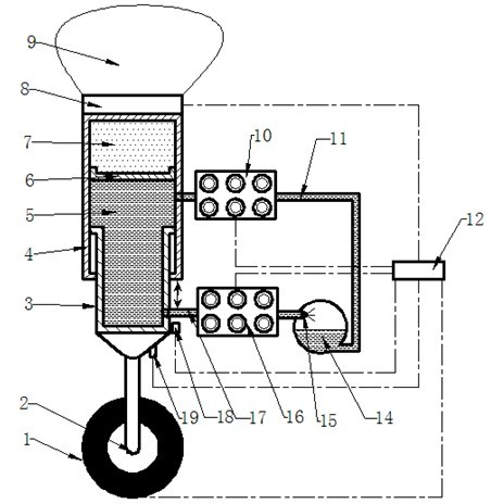
[0032] like figure 1 Shown: dual voltage drive control buffer with atomized oil chamber circuit, including wheel 1, piston rod 3, outer cylinder 4, oil chamber 5, floating piston 6, air chamber 7, oil outlet pipeline 17, first High-speed one-way switch valve group 10, external oil chamber 14, second high-speed one-way switch valve group 16, oil inlet pipeline 11

[0033] Inside the outer cylinder 4, the floating piston 6 and the piston rod 3 are arranged sequentially from top to bottom, and the piston rod 3 is arranged. Form an oil chamber 5;

[0034] An oil outlet is arranged on the piston rod 3, and the oil outlet of the piston rod 3 is connected with the oil inlet of the second high-speed one-way switch valve group 16 through the oil outlet pipeline 17, and the oil outlet of the second high-speed one-way switch valve group 16 The oil outlet of the external oil c...


PUM


Abstract

The invention relates to a flight buffer, in particular to a dual-voltage driven and controlled buffer with an atomized oil cavity loop. An oil outlet is arranged on a buffer piston rod; the oil outlet of the piston rod is connected with the oil inlet of a second high-speed unidirectional switch valve bank through an oil pipeline; the oil outlet of the second high-speed unidirectional switch valve bank is connected with the oil inlet of an external oil cavity through the oil pipeline; the oil outlet of the external oil cavity is connected with the oil inlet of a first high-speed unidirectional switch valve bank through the oil pipeline; and the oil outlet of the first high-speed unidirectional switch valve bank is connected with the oil inlet on the side wall of an outer cylinder through the oil pipeline. The main body of the dual-voltage driven and controlled buffer with an atomized oil cavity loop provided by the invention comprises an inner cylinder and an outer cylinder and is not provided with oil holes, oil needles and other oil quantity regulating components, thus the structure is simple. Double voltages are used for driving and controlling high-speed switch valves to be opened or closed, thereby increasing the response speed of the high-speed switch valves.

Description

technical field [0001] The invention relates to a flight buffer, in particular to a dual-voltage drive control buffer with an atomized oil cavity circuit. Background technique [0002] Aircraft landing gear buffer is a device in the landing gear that absorbs the impact and turbulence energy of the aircraft landing and ground movement, and acts as a buffer and shock absorber. comfort. [0003] In order to enhance the cushioning effect of the buffer, three control technologies, passive control, semi-active control and active control, have been applied in the performance control of the buffer. The passive control buffer uses the buffer itself to control the opening of the oil hole and adjust the damping. Its structure is simple, but because its system structure and parameters are fixed, once it is manufactured and installed, its work is a passive response to external excitation It is difficult to meet the needs of efficient shock absorption by changing its own characteristics...

Claims


Application Information

Patent Timeline
IPC IPC(8): F16F9/18F16F9/34F16F9/512B64C25/60
Inventor 薛彩军张莉许远聂宏张洁徐奋进
Owner NANJING UNIV OF AERONAUTICS & ASTRONAUTICS
Why Eureka
Try Eureka