

Moving load locating method used for bridge safety inspection
A positioning method and a technology of moving loads, which are applied in the direction of measuring devices and instruments, can solve the problems of inability to obtain amplitude response information and dynamic deflection information, so as to speed up the data processing cycle, simplify data acquisition equipment, and bridge detection costs Falling effect
Inactive Publication Date: 2011-06-01
SUN YAT SEN UNIV
View PDF5 Cites 13 Cited by
- Summary
- Abstract
- Description
- Claims
- Application Information
AI Technical Summary
Problems solved by technology
Integrating directly in the time domain, it turns out that the amplitude response information cannot be obtained, let alone the dynamic deflection information
Method used
View moreImage
Smart ImageViewing Examples


Examples
Embodiment 1
Embodiment 2
Embodiment 3
Login to View More PUM
 Abstract
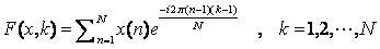
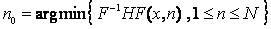
The invention provides a moving load locating method used for bridge safety inspection. A position of a moving load in a time path curve is determined by utilizing the traditional midspan vertical speed response time path signal. The cost of the bridge inspection is lowered without increasing additional special devices and the analysis of bridge kinetic response parameters is simpler, clearer andquicker. The moving load locating method is implemented by comprising the following steps of: carrying out a Fourier transform on a midspan vertical acceleration response time path signal x(t) of a bridge; corresponding a signal x(t) of a time domain to frequency domain space, and writing the signal x(t) as F(x, theta); selecting a weight function H(theta), weighting the F(x, theta), and writing the F(x, theta) as HF(x, theta); carrying out an inverse Fourier transform on the HF(x, theta), returning a signal in a frequency domain to time domain space, and writing the signal as F<-1>HF(x,t); and determining a moment of the moving load of the signal x(t) in the midspan. The moving load locating method used for the bridge safety inspection has an important significance to simplify test equipment for bridge load carrying capacity and lower test costs.
Description
technical field The invention relates to the field of bridge health detection, in particular to a moving load positioning method for bridge safety inspection. technical background In recent years, the frequent bridge collapse incidents have evolved from sporadic incidents to normal incidents, which have attracted great attention from all countries. Quick and convenient bridge safety inspection is extremely important for early warning of deteriorating bridges. Bridge safety inspection includes: bridge appearance damage inspection, bridge structure and material inspection, and bridge load test, and bridge load test includes static load test and dynamic load test. The normal operation of the bridge is to be able to withstand the dynamic impact of various large and small moving loads. Therefore, the dynamic load test of the bridge can truly reflect the health of the bridge. The dynamic impact of moving loads on various parts of the bridge is a very complicated process. Temp...
Claims
Login to View More Application Information
Patent Timeline
 IPC IPC(8): G01B21/00
Inventor毕宁
OwnerSUN YAT SEN UNIV