Locating and analyzing perforator flaps for plastic and reconstructive surgery

A technique of perforating and temporal differentiation, used in surgery, analysis using fluorescence emission, applications, etc.

Active Publication Date: 2011-06-01
STRYKER EUROPEAN OPERATIONS LIMITED
View PDF4 Cites 7 Cited by
  • Summary
  • Abstract
  • Description
  • Claims
  • Application Information

AI Technical Summary

Problems solved by technology

[0011] These questions are difficult to answer on a subjective basis

Method used


Image

  • Locating and analyzing perforator flaps for plastic and reconstructive surgery
  • Locating and analyzing perforator flaps for plastic and reconstructive surgery
  • Locating and analyzing perforator flaps for plastic and reconstructive surgery

Examples


Embodiment Construction

[0027] The present invention is directed to the pre-operative determination of the position of the perforator vessels in the perforator flap by non-invasive methods before any incision is made.

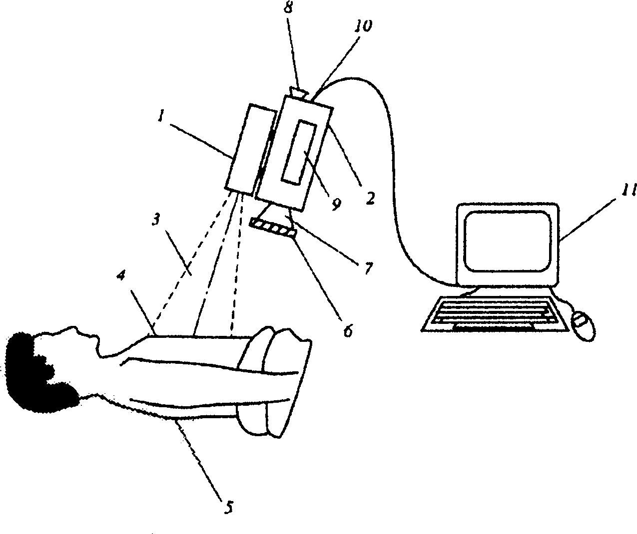
[0028] figure 1 A device for the non-invasive transcutaneous determination of tissue perfusion by means of ICG fluorescence imaging in surgical applications, in particular in preoperative applications, is schematically shown. An infrared light source, such as one or more diode lasers or LEDs, with a peak emission around 780-800 nm for exciting fluorescence in the ICG is located inside the housing 1 . The fluorescent signal is detected by a CCD camera 2 with sufficient near-infrared sensitivity; such cameras are commercially available from several vendors (Hitachi, Hamamatsu, etc.). The CCD camera 2 may have a viewfinder 8 , but the image may also be viewed during operation on an external monitor, which may be part of the electronic image processing and evaluation system 11 .

[0029...


PUM


Abstract

The present invention discloses a method and an apparatus for preoperative identification of a perforator vessel for plastic and / or reconstructive surgery using ICG fluorescence angiography imaging. Time-resolved image processing is used to highlight perforator locations and to enable visual discrimination among candidate perforators by various computed metrics Based on these metrics, the surgeon is able to interactively locate and select perforator vessels suitable for plastic and reconstructive surgery.

Description

[0001] Cross References to Related Applications [0002] This application claims priority to US Provisional Application Serial No. 61 / 044,779, filed April 14, 2008, which is hereby incorporated by reference in its entirety. Background technique [0003] Plastic and reconstructive surgery often requires positioning and clinical evaluation of a flap of skin and subcutaneous tissue fed by an isolated perforating vessel and potentially suitable for transplantation into another part of the body. Perforators pass from their source vessels through or between deep musculature to the skin surface. Well vascularized flaps are good candidates for transplantation. [0004] For example, abdominal donor site flaps have become the standard for autologous breast reconstruction since the 1780s. Within the abdomen, free fat is selectively distributed ranging from intact transverse rectus abdominis muscle (TRAM) flaps to isolated perforator flaps such as the deep inferior epigastric artery (DI...

Claims


Application Information

Patent Timeline
Patent Type & Authority Applications(China)
IPC IPC(8): A61B5/0275
CPCA61B5/0071A61B5/489A61B5/0059A61B5/0077A61B5/0261A61B5/0275A61B5/7239A61B5/7242A61B5/7425A61B5/743A61B2576/02G16H30/40A61B5/0265
Inventor P·德沃尔斯基D·M·H·戈耶特
Owner STRYKER EUROPEAN OPERATIONS LIMITED
Why Eureka
Try Eureka