
Foam ceramic composite filtering method for high-temperature alloy in centrifugal field

A technology of foam ceramics and superalloys, applied in the direction of improving process efficiency, etc., can solve problems such as increasing the pressure head or gas pressurization, clogging, and the cleanliness of the master alloy and the returned material cannot meet the requirements for the purification of the superalloy melt. Achieve the effect of simple method, convenient operation and high utilization rate of alloy

Inactive Publication Date: 2011-06-08
NANCHANG HANGKONG UNIVERSITY
View PDF4 Cites 8 Cited by
  • Summary
  • Abstract
  • Description
  • Claims
  • Application Information

AI Technical Summary

Problems solved by technology

However, the smaller the ceramic channel, the greater the thickness of the filter element, the greater the resistance to the flow of the alloy melt, and a higher flow pressure head is required to pass through. At the same time, the foamed ceramics with small pore size are easily blocked by larger inclusion particles. Not suitable for direct use
Since there are a variety of active alloying elements in the superalloy, in order to prevent the alloying elements from oxidizing and burning and forming inclusions, the superalloys used in aviation are all vacuum smelted. This smelting method limits the use of increasing the height of the liquid column and increasing the pressure head for the alloy melt. or the possibility of gas pressurization
In the existing high-temperature alloy foam ceramic filtration process, the minimum size of the foam ceramic pores does not exceed 20ppi, and the cleanliness of the master alloy and the returned material cannot meet the requirements of modern aero-engine manufacturing for the purification of high-temperature alloy melts

Method used


Image

  • Foam ceramic composite filtering method for high-temperature alloy in centrifugal field
  • Foam ceramic composite filtering method for high-temperature alloy in centrifugal field

Examples


Embodiment 1

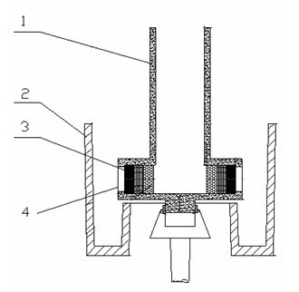
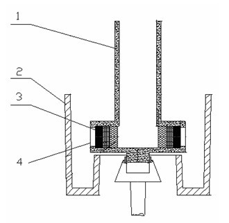
[0009] The present invention is realized like this, method step is: Prefabricate a special-type high-temperature resistant ceramic sprue 1 composed of a sprue and two outlet channels perpendicular to the sprue. The axes of the two outlet channels are on a horizontal plane and at an angle of 180°; each sprue outlet channel is placed 4 pieces of ceramic foam filters 3, the ceramic foam filters 3 are stacked in the outlet channel 4 from the inside to the outside in the order of coarse pores to fine pores, the hole size and thickness of the ceramic foam filters 3 are 10ppi-20mm, 20ppi respectively -20mm, 40ppi-20mm, 60ppi-20mm, the total thickness of the foam ceramic filter is 80mm; The high temperature resistant ceramic sprue is fastened in the centrifugal device, and the axis of the sprue coincides with the rotation axis of the centrifugal device; Preheat the sprue to 1000°C before pouring; The centrifugal device is started, and the rotational speed of the centrifugal devi...

Embodiment 2

[0011] The present invention is realized like this, method step is: Prefabricate a special high-temperature resistant ceramic sprue composed of a sprue and 4 outlet channels perpendicular to the sprue. The axes of the 4 outlet channels are on a horizontal plane and at an angle of 90°; each sprue outlet channel is placed 4 A ceramic foam filter, the ceramic foam filter is stacked in the outlet channel from the inside to the outside in the order of coarse pores to fine pores, the hole size and thickness of the ceramic foam filter are 10ppi-20mm, 20ppi-20mm, 40ppi- 20mm, 60ppi-20mm, the total thickness of the foam ceramic filter is 80mm; The high temperature resistant ceramic sprue is fastened in the centrifugal device, and the axis of the sprue coincides with the rotation axis of the centrifugal device; Preheat the sprue to 1000°C before pouring; Start the centrifugal device, the rotating speed of the centrifugal device is 500r / min, and then pour the alloy, and the superal...

Embodiment 3

[0013] The present invention is realized like this, method step is: Prefabricate a special high-temperature resistant ceramic sprue consisting of a sprue and an annular outlet channel coaxial with the sprue. The annular sprue has a built-in cylindrical foam ceramic filter, and the hole size and thickness are 10ppi-20mm, respectively. 20ppi-20mm, 40ppi-20mm, 60ppi-20mm, nested in turn, the total thickness of the foam ceramic filter cylinder is 50mm; When the high temperature resistant ceramic sprue is placed in the centrifugal device, the axis of the sprue coincides with the rotation axis of the centrifugal device; Preheat the sprue to 1000°C before pouring; Start the centrifugal device, the rotating speed of the centrifugal device is in the range of 500r / min, and then pour the alloy, and the superalloy melt will pass through the filter medium under the action of centrifugal force.

[0014] Such as figure 1 Said, the above-mentioned centrifugal force field ceramic foam c...


PUM


Abstract

The invention discloses a foam ceramic composite filtering method for a high-temperature alloy in a centrifugal field. The method comprises the following steps: (1) prefabricating a special-shape refractory ceramic runner combining a sprue and an outlet channel vertical to the sprue, and placing multiple foam ceramic filtering sheets in the outlet channel of the runner; (2) superposing the axis of the sprue on the rotation axis of a centrifuge device; (3) before pouring, preheating the runner and the foam ceramic sheets to over 1000 DEG C; and (4) starting the centrifuge device to rotate the runner, wherein the rotation speed of the centrifuge device ranges from 10 r / min to 3,000 r / min; and pouring the high-temperature alloy melt which passes through the foam ceramic filtering sheets under the action of centrifugal force. The invention has the advantages that: the method is simple and convenient to operate; and after the high-temperature alloy is purified, the removal rate of oxides larger than 1 mu m can reach over 90%, and the purification requirements on the mother alloy or returns of the high-temperature alloy in the manufacturing of modern aircraft engines are completely met.

Description

technical field [0001] The invention relates to a composite filtration method of foam ceramics, in particular to a composite filtration method of foam ceramics in a superalloy centrifugal force field. Background technique [0002] With the continuous improvement of the performance of modern aero-engines, the requirements for the cleanliness of high-temperature alloy materials for aero-engines are also getting higher and higher. In the existing aero-engine manufacturing technology, foam ceramics are generally used to filter superalloy master alloys and return materials. It is a filter medium with a deep bed filtration mechanism. It relies on a large number of changeable small ceramic channels to capture the inclusion particles in the alloy melt through three mechanisms: mechanical barrier, surface adsorption and speed-down sedimentation, so that the alloy The melt reaches a higher degree of purification. The smaller the porosity of ceramic foam, the finer the ceramic channel...

Claims


Application Information

Patent Timeline
IPC IPC(8): C22B9/02
CPCY02P10/20
Inventor 王薇薇余欢戴斌煜商景利
Owner NANCHANG HANGKONG UNIVERSITY
Learn More