
Measuring device and measuring method for position of reticle stage of scanning lithography

A technology of measuring device and mask stage, which is applied in the direction of photolithography process exposure device, microlithography exposure equipment, etc. restrictions, etc.

Active Publication Date: 2011-06-08
SHANGHAI MICRO ELECTRONICS EQUIP (GRP) CO LTD
View PDF0 Cites 8 Cited by
  • Summary
  • Abstract
  • Description
  • Claims
  • Application Information

AI Technical Summary

Problems solved by technology

[0004] The technical defects existing in the prior art mainly include the following aspects: (1) the types of the horizontal measurement sensor and the vertical measurement sensor are inconsistent, which makes the signal synchronization of the two measurement systems poor; (2) the measurement of the capacitive sensor itself The range and linear area are limited, which requires the bottom of the mask table to be very close to the top of the objective lens, which is not conducive to the installation and layout of other sensors; (3) With the continuous reduction of the critical dimension of the exposure line, the requirements for image quality are increasing High, so more precise vertical control of the mask table is required, and due to the existence of fringe electric field effects, the resolution of capacitive sensors is limited, making it difficult to apply to more precise lithography machines; (4) capacitive sensors are electrical Measurement, the sensor on the top of the objective lens and the measurement plate on the bottom of the mask table require a dedicated circuit, which brings inconvenience to the design of the mask table
[0005] Therefore, with the development of semiconductor technology and the further reduction of the size of integrated circuit devices, it is difficult for the existing technology to measure the position of the mask table to meet the needs of high-precision, high-resolution scanning lithography machines.

Method used


Image

  • Measuring device and measuring method for position of reticle stage of scanning lithography
  • Measuring device and measuring method for position of reticle stage of scanning lithography
  • Measuring device and measuring method for position of reticle stage of scanning lithography

Examples


Embodiment Construction

[0020] In order to make the object, technical solution and advantages of the present invention clearer, the present invention will be further described in detail below in conjunction with the accompanying drawings.

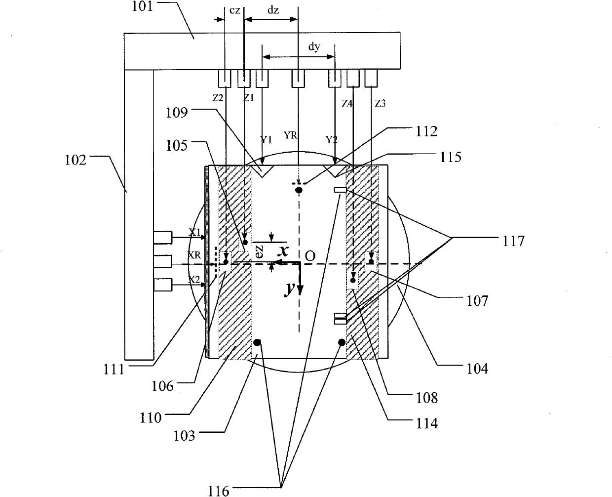
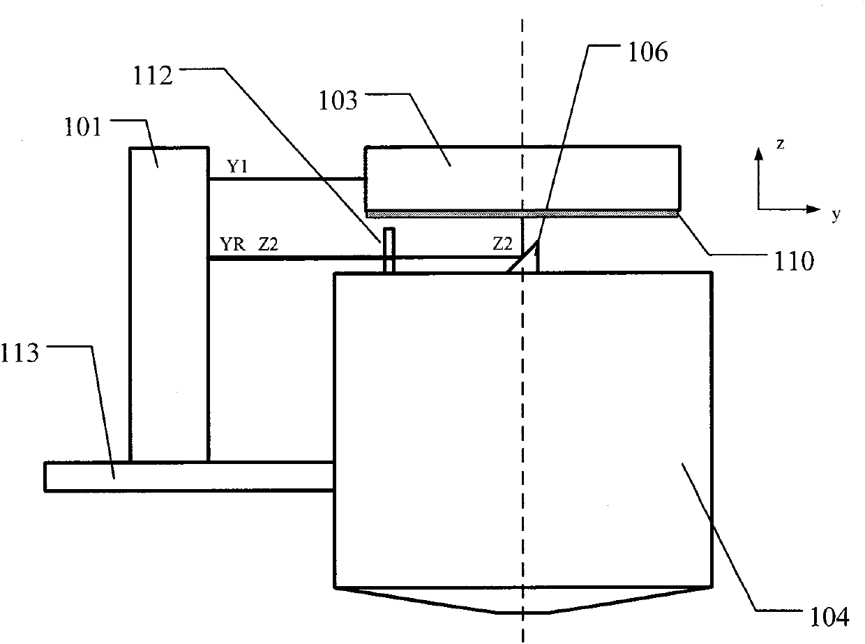
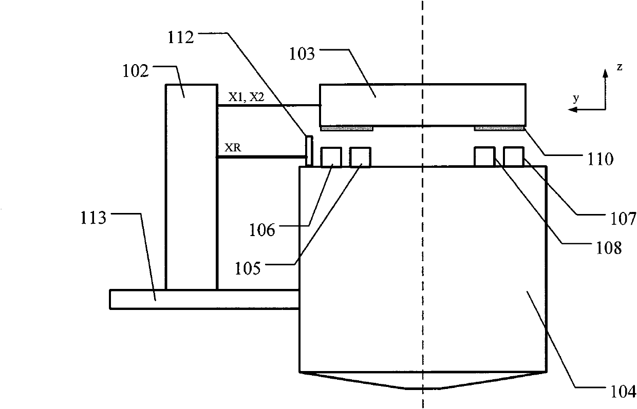
[0021] figure 1 A top view of the mask table position measuring device of the scanning lithography machine provided by the present invention, figure 2 , image 3 respectively figure 1 Left and front views of the mask stage position measuring device of the scanning lithography machine shown.

[0022] Such as Figure 1 ~ Figure 3 As shown, in this specific embodiment, the device for measuring the position of the mask stage of a scanning lithography machine includes: a horizontal longitudinal (y-direction) measurement module 101, a horizontal horizontal (x-direction) measurement module 102, a mask stage 103, an objective lens 104 and main substrate 113 . Wherein, the horizontal longitudinal (y-direction) measurement module 101 and the horizontal transverse (x-d...


PUM


Abstract

A measuring device and a measuring method for the position of a reticle stage of a scanning lithography. Several laser interferometers are adopted in stead of capacitance sensors to allow the sensors in the horizontal and the vertical directions to be consistent, so the synchronous control of signals is convenient and the measuring range measured in the vertical direction is increased. In addition, interferometric light can be introduced from any horizontal direction by mounting a 45-degree reflector at the top of the objective, so measurements in the vertical direction can be carried out within a large moving range; and weight distribution of the interferometers measuring in every direction is introduced during the measurement of the inclination amount, so the measurement of the reticle stage position is more accurate.

Description

technical field [0001] The invention relates to a position measuring device and a measuring method, in particular to a position measuring device and a measuring method for a mask table of a lithography machine, and belongs to the technical field of control adjustment systems and orientation measurement. Background technique [0002] During the lithography exposure process, the mask stage and the workpiece stage of the scanning lithography machine need to move relative to each other for scanning. In order to make the pattern on the reticle imaged on the corresponding position on the silicon wafer with good imaging quality, it is necessary to obtain the mask stage in the horizontal direction (X direction), horizontal direction (Y direction), horizontal direction (Y direction), The position information on the 6 degrees of freedom of the tilt Rz in the vertical direction (Z direction), the tilt Rz in the vertical direction (Z direction), the tilt Rx around the horizontal directi...

Claims


Application Information

Patent Timeline
IPC IPC(8): G03F7/20
Inventor 许琦欣
Owner SHANGHAI MICRO ELECTRONICS EQUIP (GRP) CO LTD
Learn More