
Shallow trench isolation method

A shallow trench and trench technology, applied in electrical components, semiconductor/solid-state device manufacturing, circuits, etc., can solve the problems of steepness and poor isolation effect of trench 101, so as to improve the isolation effect and reduce the difficulty of the etching process Effect

Inactive Publication Date: 2011-06-08
CSMC TECH FAB1 +1
View PDF8 Cites 5 Cited by
  • Summary
  • Abstract
  • Description
  • Claims
  • Application Information

AI Technical Summary

Problems solved by technology

[0005] However, the corners at the top of the shallow trench formed by the existing shallow trench isolation technology are generally relatively steep, please refer to figure 1 , figure 1 It is a schematic diagram of forming a shallow trench 101 in a substrate 100 using the prior art. The corner 102 of the trench 101 formed using the prior art is relatively steep, so that the isolation effect of the trench 101 after filling the isolation medium is comparatively Difference

Method used


Image

  • Shallow trench isolation method
  • Shallow trench isolation method
  • Shallow trench isolation method

Examples


Embodiment Construction

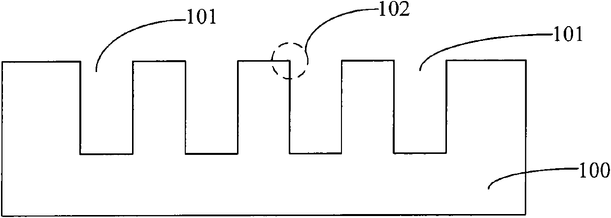
[0028] The corners of the top of the shallow trench formed by the existing shallow trench isolation technology are generally relatively steep, so that the isolation effect of the trench after filling the isolation medium is relatively poor.

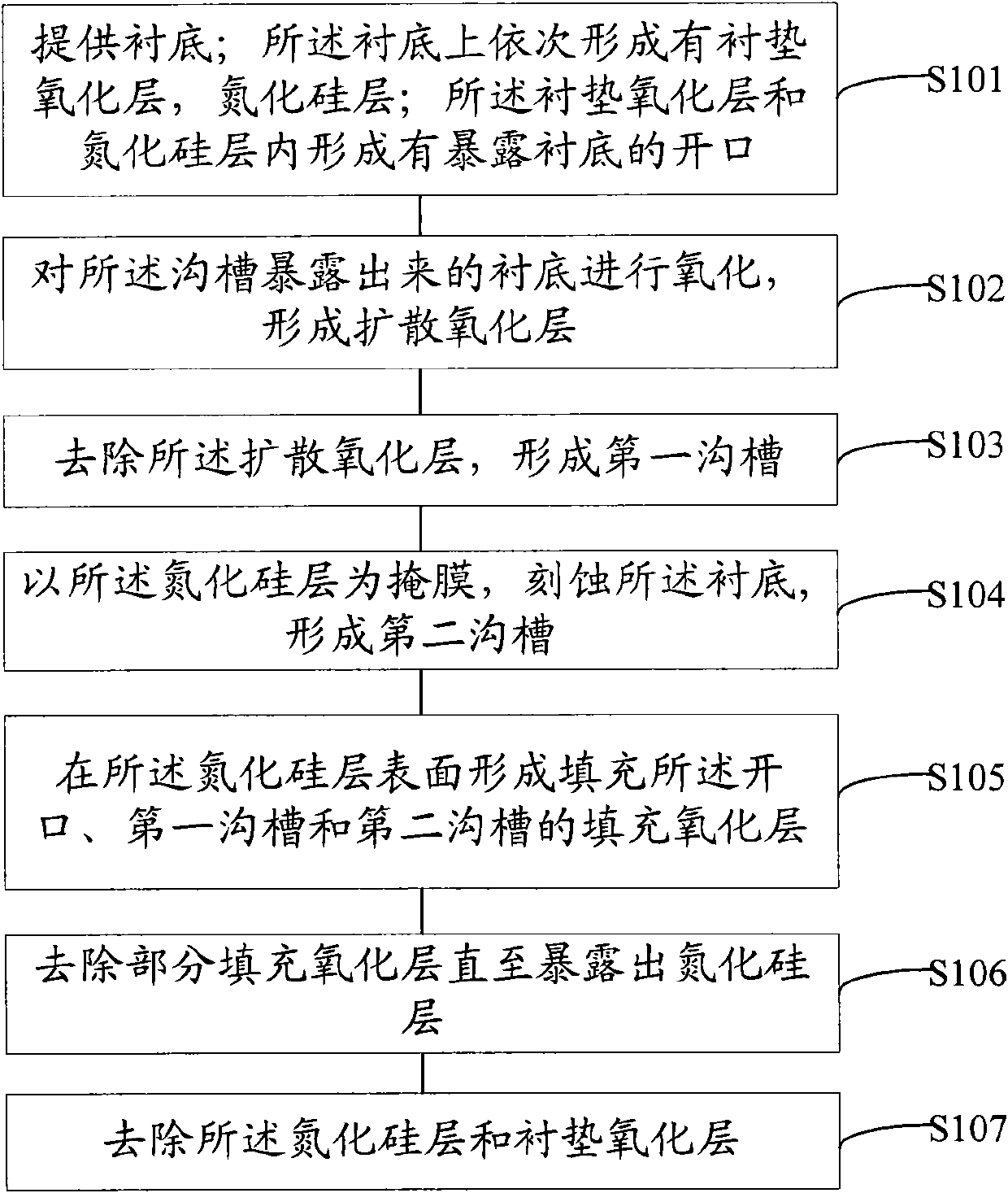
[0029] For this reason, the inventor of the present invention provides a shallow trench isolation method, including:

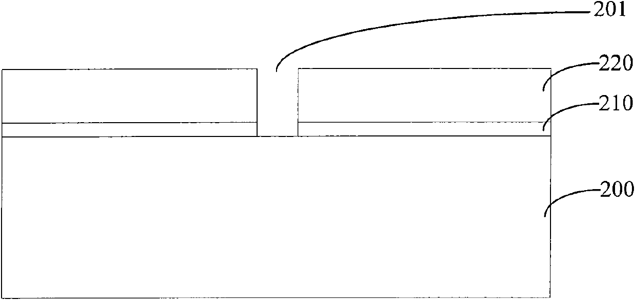
[0030] A substrate is provided; a pad oxide layer and a silicon nitride layer are sequentially formed on the substrate; openings for exposing the substrate are formed in the pad oxide layer and the silicon nitride layer;

[0031] Oxidizing the substrate exposed by the trench to form a diffused oxide layer;

[0032] removing the diffusion oxide layer to form a first trench;

[0033] using the silicon nitride layer as a mask, etching the substrate to form a second trench;

[0034] forming a filling oxide layer filling the opening, the first trench and the second trench on the surface of the silicon nitride layer;

[0035...


PUM


Abstract

The present invention relates to a shallow trench isolation method, which comprises the following steps: providing a substrate; forming a liner oxide layer and a silicon nitride layer on the substrate successively forming an opening which exposes the substrate in the liner oxide layer and the silicon nitride layer; carrying out an oxidation of the substrate which is exposed from the trench to form a diffusion oxide layer; removing the diffusion oxide layer, and forming a first trench; etching the substrate by using the silicon nitride layer as a mask layer, and forming a second trench; forming a filling oxide layer which is used for filling the opening, the first trench and the second trench -on the surface of the silicon nitride layer; and removing part of the filling layer until the silicon nitride layer is exposed; removing the silicon nitride layer and the liner oxide layer. The shallow trench generated by the shallow trench isolation method provided by the present invention has a radian top corner and improves isolation effect of a shallow trench.

Description

technical field [0001] The invention relates to the field of semiconductor manufacturing, in particular to a shallow trench isolation method. Background technique [0002] Shallow Trench Isolation (STI) is a device isolation technology. The principle of shallow trench isolation structure preparation is to etch a groove on the surface of the silicon substrate corresponding to the shallow trench, and use chemical vapor deposition (Chemical Vapor Deposition, CVD) to deposit silicon dioxide (SiO 2 ) into the groove. [0003] As the semiconductor technology enters the deep sub-micron era, components below 0.18 microns, such as active area isolation layers of MOS circuits, are mostly produced using shallow trench isolation technology. More information on shallow trench isolation can be found in US Patent No. US7112513 Information about trench isolation technology. [0004] The specific process of the shallow trench isolation technology includes: forming a shallow trench on the ...

Claims


Application Information

Patent Timeline
IPC IPC(8): H01L21/762
Inventor 余心梅邵永军赵志勇张明敏
Owner CSMC TECH FAB1
Learn More