
Communication network element and clock frequency correction system and method

A clock frequency and correction system technology, applied in the field of communication, can solve problems such as complex algorithms, affecting efficiency, increasing large synchronization messages, etc.

Inactive Publication Date: 2011-06-08
李奇 +4
View PDF0 Cites 22 Cited by
  • Summary
  • Abstract
  • Description
  • Claims
  • Application Information

AI Technical Summary

Problems solved by technology

In contrast, the solution of using the peer communication network element to implement the NTP server does not need to introduce a third-party network element, which has certain advantages, but there are also certain defects in implementing the NTP server function on the peer communication network element, that is, the communication Both sides also need to add a large number of synchronization messages, which occupy precious transmission bandwidth resources. At the same time, a large number of synchronization messages will also affect the efficiency of the underlying hardware of the network element in processing other types of messages.
[0005] (2) When the PTP protocol is used to correct the clock frequency, because the algorithm adopted by the PTP protocol is more complex, the correction result is better than that of the NTP protocol. Bandwidth and issues that affect the efficiency of the underlying hardware of network elements in processing other types of packets
[0006] (3) The NTP protocol and the PTP protocol are both standard protocols, which use fixed port numbers to transmit synchronous messages. However, in an IP network, messages will inevitably pass through many routers. If certain fixed ports are prohibited on the router If the data is sent, the synchronization message may not be transmitted to the destination, so that the clock frequency correction cannot be completed

Method used


Image

  • Communication network element and clock frequency correction system and method
  • Communication network element and clock frequency correction system and method
  • Communication network element and clock frequency correction system and method

Examples


Embodiment Construction

[0069] In the embodiment of the present invention, the existing RTP (Real Time Transport Protocol, real-time transport protocol) / RTCP (Real Time Control Protocol, real-time transport control protocol) protocol is used to realize the correction of the clock frequency of the communication network element without introducing a third party network element, which reduces the system cost and the complexity of networking. In addition, there is no need to add a large number of synchronization messages between the communication network element as the clock reference source and the communication network element to be corrected, so as not to affect the transmission bandwidth and the communication network. Efficiency of the underlying hardware for processing other types of packets.

[0070] The following briefly describes the RTP / RTCP protocol.

[0071] The RTP / RTCP protocol is a transmission protocol for multimedia data streams on the Internet (Ethernet). Among them, the RTP message is u...


PUM


Abstract

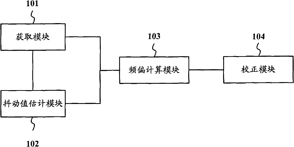
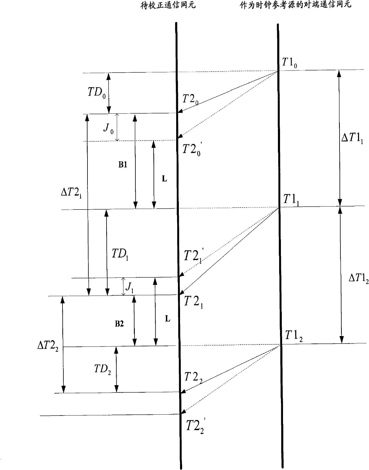
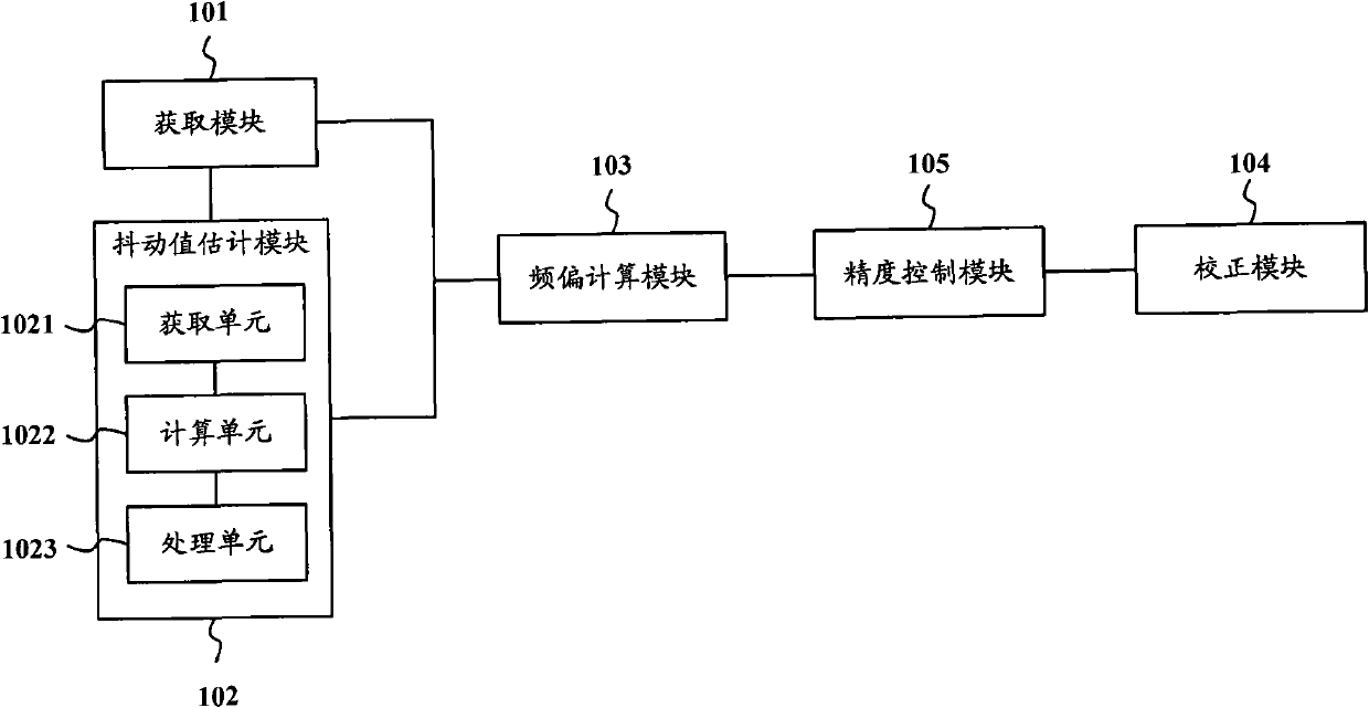
The invention provides a communication network element, a clock frequency correction system and method. The communication network element comprises an acquisition module, a jitter value estimation value, a frequency offset calculation module and a correction module, wherein the acquisition module is used for acquiring a packet transmitting time stamp value and a local packet receiving time stamp value which are carried in an RTCP (Real-Time Control Protocol) message when the RTCP message which serves as a clock reference clock and is transmitted by an opposite end communication network element is received; the jitter value estimation module is used for estimating the jitter value of the RTCP message; the frequency offset calculation module is used for calculating a clock frequency offset according to the packet transmitting time stamp value, the packet receiving time stamp value and the jitter value of the RTCP message; and the correction module is used for correcting a time frequency according to the clock frequency offset. By adopting the system and the method, clock frequency can be corrected easily and effectively.

Description

technical field [0001] The invention relates to the technical field of communication, in particular to a communication network element, a clock frequency correction system and a correction method. Background technique [0002] The flexible and diverse characteristics of IP (Internet Protocol, Internet Protocol) network networking have made the IP networking mode more and more common. Due to cost considerations, most communication network elements in the IP network do not use constant temperature crystal oscillators to generate the necessary clock frequency for communication network elements, but use cheaper temperature-controlled crystal oscillators, etc., because the temperature-controlled crystal oscillators are not stable enough. After the time runs, the clock frequency of the communication network element may deviate to a certain extent, thereby affecting the normal operation of the service. For example, in the IP base station system, when the clock frequency of the bas...

Claims


Application Information

Patent Timeline
Patent Type & Authority Applications(China)
IPC IPC(8): H04L12/56H04L29/06
Inventor 陆敬明代言非刘晓燕妙文婷
Owner 李奇
Learn More