Method and arrangement to enhance the preheating of a fuel cell system

A fuel cell system and fuel cell technology, applied in the direction of fuel cell heat exchange, fuel cells, fuel cell additives, etc., can solve the problems of space occupation, explosion, high equipment cost, etc., and achieve energy cost reduction, high-efficiency heat transfer, The effect of heat transfer saving

Inactive Publication Date: 2011-06-08
WARTSILA FINLAND OY
View PDF5 Cites 1 Cited by
  • Summary
  • Abstract
  • Description
  • Claims
  • Application Information

AI Technical Summary

Problems solved by technology

Therefore, when heating the safety gas on the anode side, there is always a risk of exceeding the hydrogen concentration or the temperature of the safety gas (e.g. due to a fault event), resulting in a potential explosion hazard
A separate heating system for the anode side with the possible safety devices included therein also leads to considerable equipment costs while taking up space

Method used


Image

  • Method and arrangement to enhance the preheating of a fuel cell system
  • Method and arrangement to enhance the preheating of a fuel cell system
  • Method and arrangement to enhance the preheating of a fuel cell system

Examples


Embodiment Construction

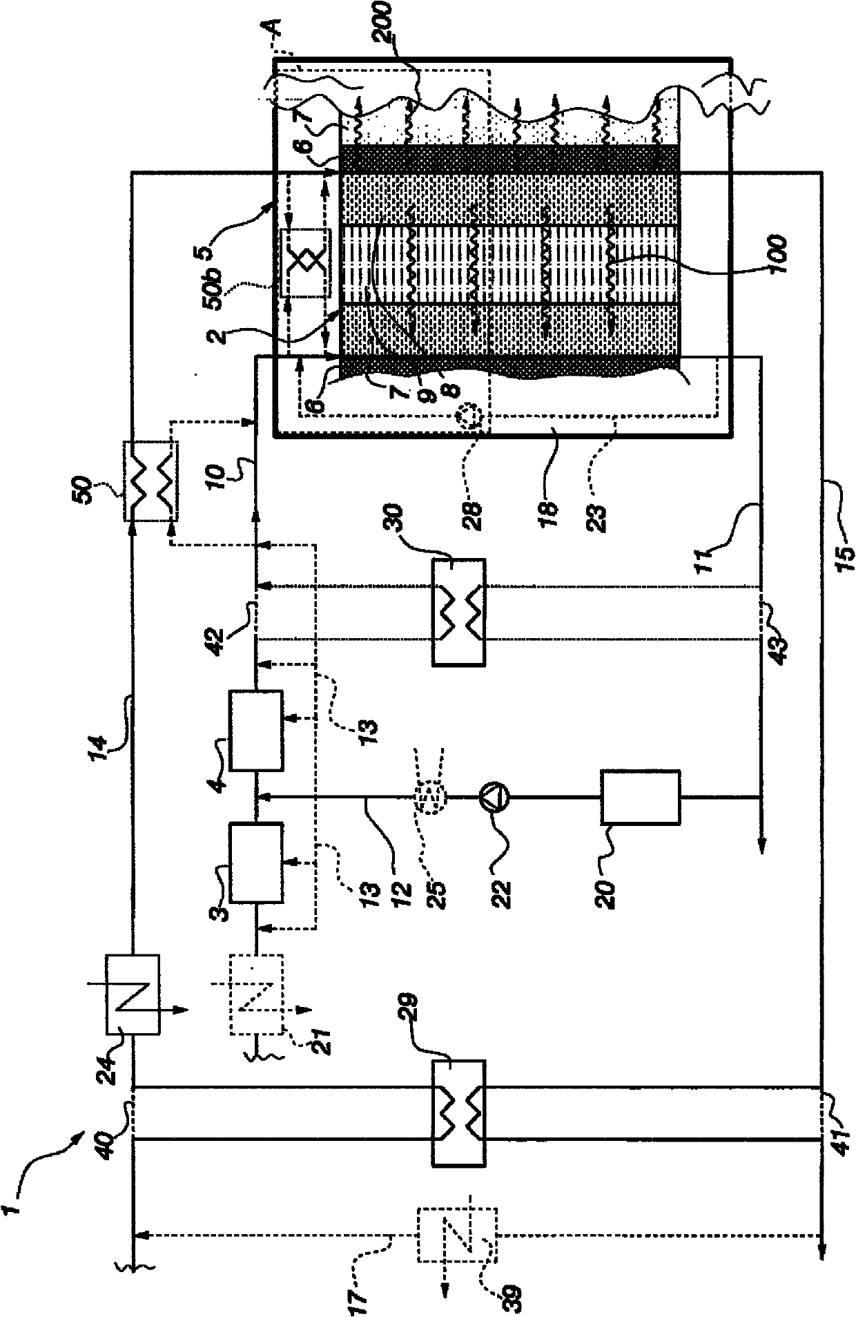
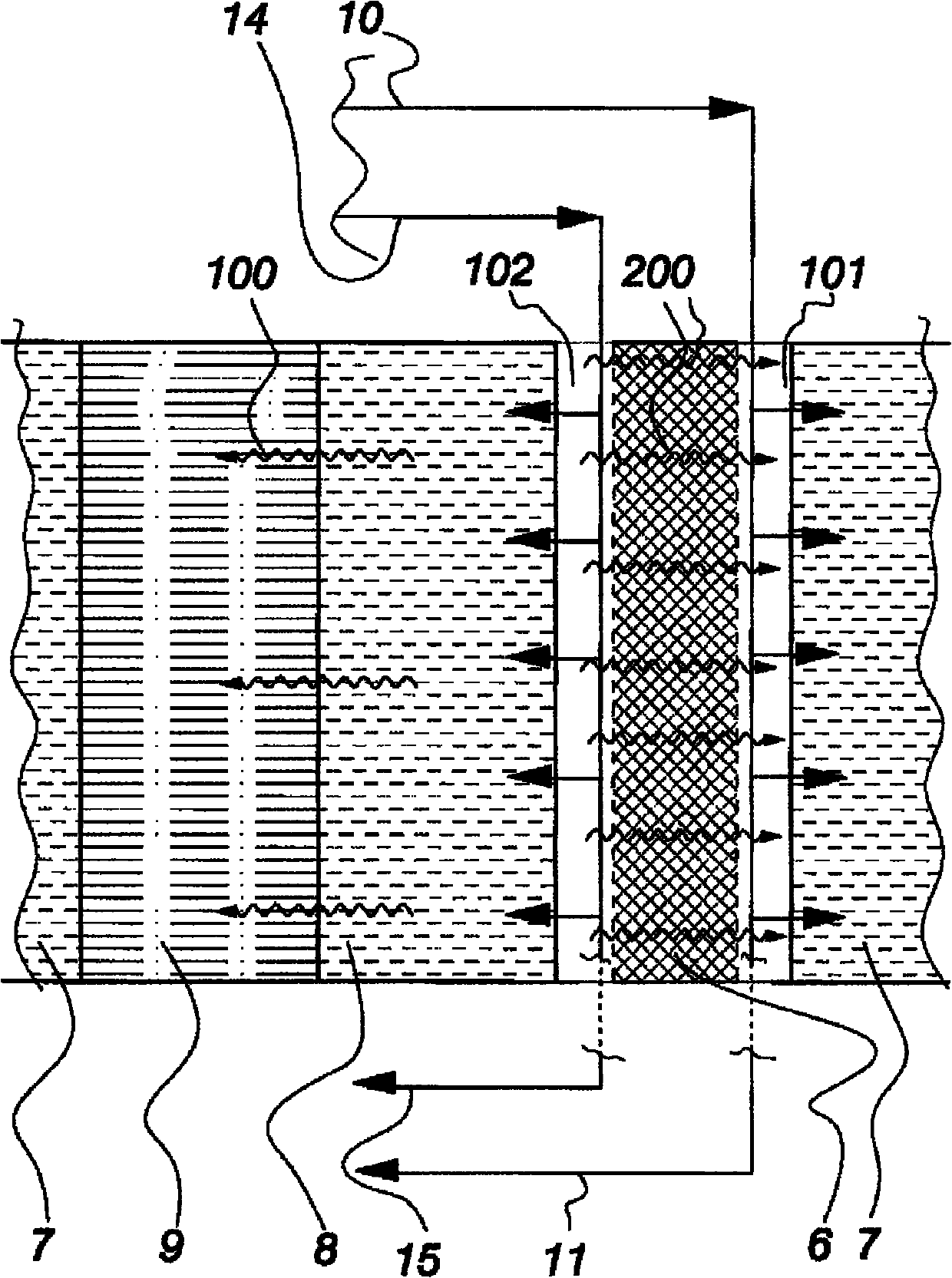
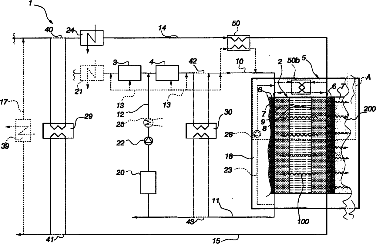
[0012] figure 1 The fuel cell system 1 is shown in a highly schematic view. The fuel cell unit 5 included in the fuel cell system 1 includes one or more fuel cell stacks consisting of fuel cells 2 connected continuously in series and connection plates 6 called interconnects provided between the individual fuel cells. , the fuel cell 2 is characterized by an anode side 7 , a cathode side 8 and an electrolyte 9 arranged between the anode side 7 and the cathode side 8 . The connecting plate 6 is preferably designed as a kind of bipolar plate, i.e. it is located on the cathode side of one individual fuel cell 2 and on the anode side of the other individual fuel cell 2, and acts as a link between the fuel cells between them. It acts as an electrical conductor between cells and as a gas barrier that blocks the uncontrolled flow of gas between cells. Most importantly, however, it provides a flow channel system on both the anode side and the cathode side for the gas to flow in the f...


PUM


Abstract

The invention relates to a method to enhance the preheating of a fuel cell system (1), said fuel cell system (1) comprising at least one fuel cell unit (5) whose fuel cells (2) are provided with an anode side (7), a cathode side (8) and an electrolyte (9) provided there between, as well as a connecting plate (6) set between each of the fuel cells (2). In the method, a safety gas flowing on the anode side (7) is heated, at least for the most part, in the fuel cell unit (5) by means of thermal energy contained in a gas flowing on the cathode side (8). The invention relates also to a fuel cell system implementing the method.

Description

technical field [0001] The object of the present invention is a method of enhancing the preheating of a fuel cell system comprising at least one fuel cell unit, the fuel cells of which are provided with an anode side, a connecting plate arranged between the individual fuel cells, A cathode side and an electrolyte disposed between the anode side and the cathode side. Another object of the invention is a fuel cell system applying the method. Background technique [0002] The present invention relates to fuel cell systems, which operate at high temperatures and generally require a long warm-up process to initiate practical operation. In fact, the present invention is especially useful in SOFC (Solid Oxide Fuel Cell: Solid Oxide Fuel Cell) and MCFC (Molten Carbonate Fuel Cell: Molten Carbonate Fuel Cell) type fuel cell systems, which are heated to operating temperatures that may It can take up to several hours. The heating of the fuel cell continues until it reaches a tempera...

Claims


Application Information

Patent Timeline
Patent Type & Authority Applications(China)
IPC IPC(8): H01M8/04
CPCH01M8/0618Y02E60/50H01M8/04097H01M8/04014Y02E60/526H01M8/04268H01M2008/1293Y02E60/525H01M8/0675H01M2008/147H01M8/04H01M8/12H01M8/14
Inventor 特罗·霍蒂宁金·阿斯特罗姆蒂莫·基维萨里尤卡·古斯
Owner WARTSILA FINLAND OY
Why Eureka
Try Eureka