Method and device for controlling clogging of filler layer of biofiltration device

A filter device and biological filtration technology, applied in the field of environmental governance, can solve problems such as plugging of packing layers, achieve the effect of reducing maintenance costs and prolonging stable operation time

Active Publication Date: 2011-06-15
TIANJIN UNIV
View PDF2 Cites 3 Cited by
  • Summary
  • Abstract
  • Description
  • Claims
  • Application Information

AI Technical Summary

Problems solved by technology

[0004] The purpose of the present invention is to solve the problem of clogging of the filler layer caused by excessive biomass accumulation in the traditional biological filter device, and to provide a method for controlling the clogging of the filler layer of the biological filter device

Method used


Image

  • Method and device for controlling clogging of filler layer of biofiltration device
  • Method and device for controlling clogging of filler layer of biofiltration device

Examples


Embodiment 1

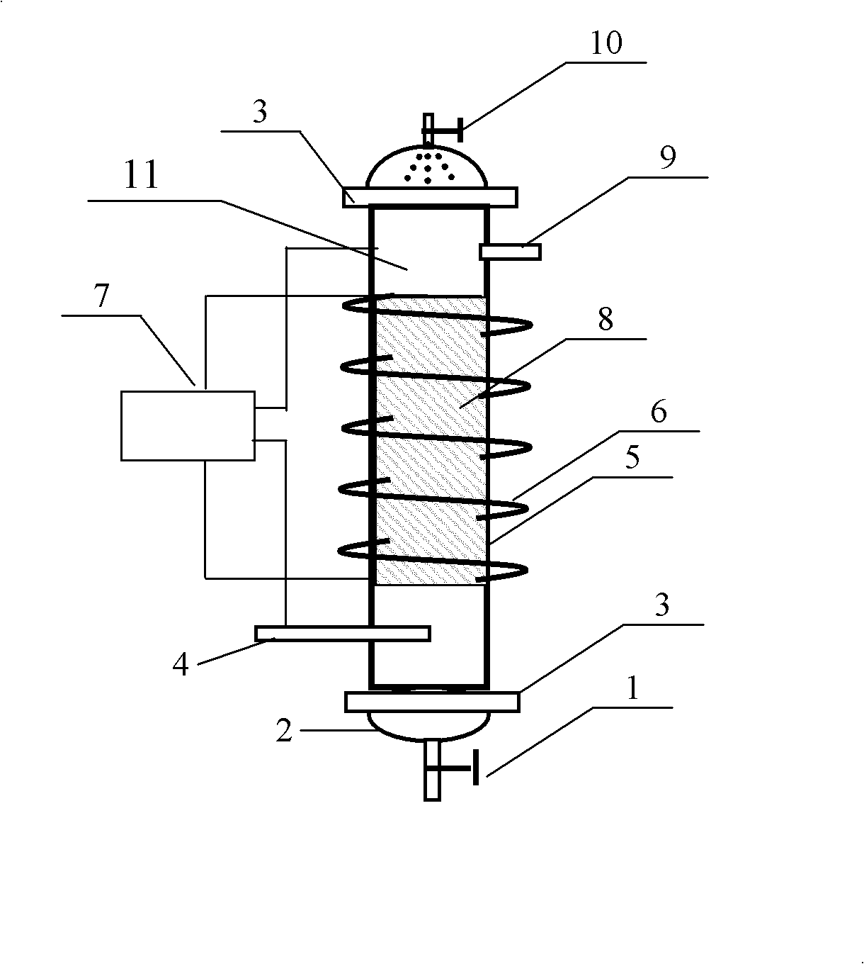
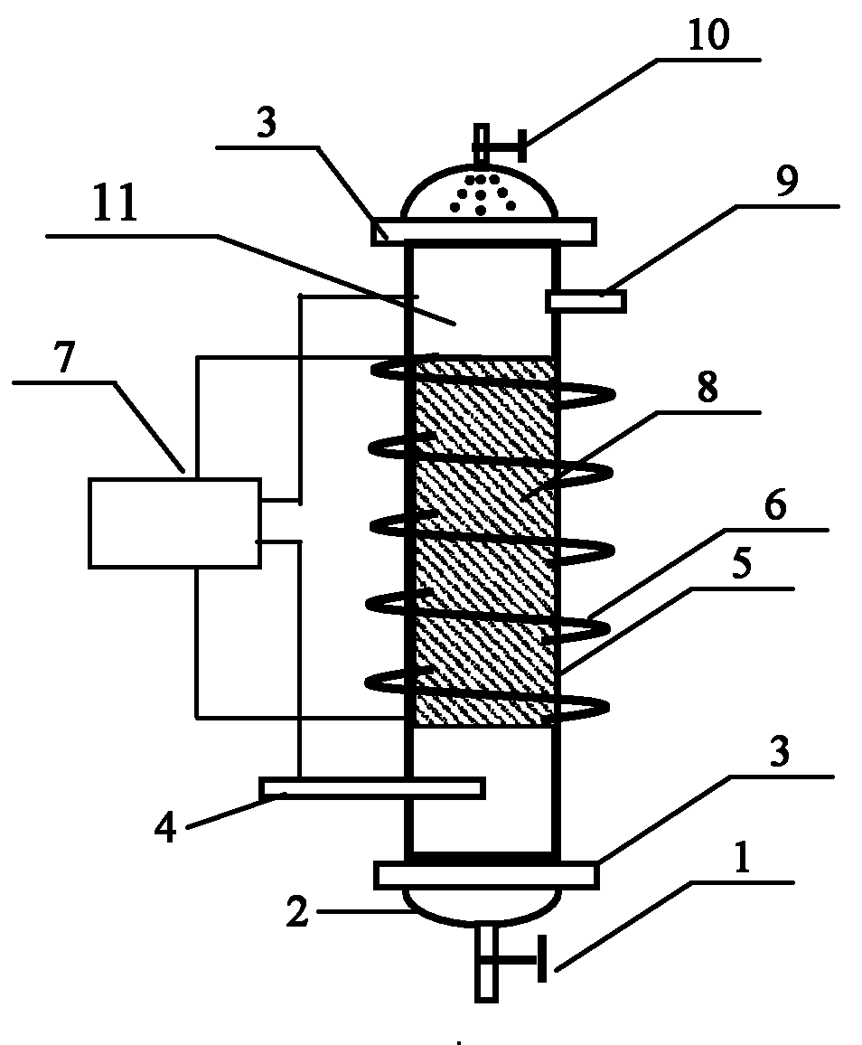
[0025] Use an electric heating rod to heat the air to 60°C (relative humidity is 65%), with a gas flow rate of 0.1m 3 / h into a biofiltration device with an effective volume of 3.1L (300-500mg / m has been treated for 70 consecutive days -3 toluene gas), the superficial flow velocity of the gas in the biological filter device is 0.6m / min, and the electric heating belt wound on the outer wall of the biological filter device is used to ensure that the outlet gas temperature is not lower than 55°C. After 30 minutes of high-temperature gas, The pressure drop of the packing layer of the biological filter device is 5mm water column. Under the same conditions, the pressure drop of the packing layer is 20mm water column for the biofiltration device that is fed with normal temperature (35°C) gas.

Embodiment 2

[0027] Use an electric heating rod to heat the air to 60°C (relative humidity is 65%), with a gas flow rate of 0.2m 3 / h into a biofiltration device with an effective volume of 3.1L (300-500mg / m has been treated for 70 consecutive days -3 toluene gas), the superficial flow velocity of the gas in the biological filter device is 1.2m / min, and the electric heating belt wrapped around the outer wall of the biological filter device is used to ensure that the outlet gas temperature is not lower than 58°C. After 30 minutes of high-temperature gas, The pressure drop of the packing layer of the biological filter device is 5mm water column. Under the same conditions, the pressure drop of the packing layer is 20mm water column for the biofiltration device that is fed with normal temperature (35°C) gas.

Embodiment 3

[0029] Use an electric heating rod to heat the air to 65°C (relative humidity is 65%), with a gas flow rate of 0.1m 3 / h into a biofiltration device with an effective volume of 3.1L (300-500mg / m has been treated for 70 consecutive days -3 toluene gas), the superficial flow velocity of the gas in the biological filter device is 0.6m / min, and the electric heating belt wound on the outer wall of the biological filter device is used to ensure that the outlet gas temperature is not lower than 55°C. After 30 minutes of high-temperature gas, The pressure drop of the packing layer of the biological filter device is 6mm water column. Under the same conditions, the pressure drop of the packing layer is 20mm water column for the biofiltration device that is fed with normal temperature (35°C) gas.


PUM


Abstract

The invention discloses a method and device for controlling clogging of a filler layer of a biofiltration device. The method disclosed by the invention comprises the following steps: heating the biofiltration device by a heating device and a coating of heat-conductive material, then introducing high-temperature gas (of which the temperature is not below 60 DEG C and the relative humidity is not below 50%) into the biofiltration device, particularly heating the section from a gas inlet to a gas outlet in the device, and keeping the gas temperature at the gas inlet and the gas temperature at the gas outlet not below 55 DEG C by the feedback control of a controller. By adopting the biofiltration device into which the high-temperature gas is introduced, the damaging effect of the high-temperature gas on microbial cells is used, thereby reducing the biomass in the biofiltration device, effectively controlling the problems of pressure drop and clogging of the filler layer, being applicable to biofiltration devices for treating various waste gases, and decreasing the maintenance cost brought about by clogging of the filler layer.

Description

technical field [0001] The invention belongs to the technical field of environmental treatment, and more specifically relates to a technology for solving the plugging of a packing layer in a biological filter device for treating malodorous and volatile organic gases. Background technique [0002] Odor and volatile organic compound pollution are one of the main reasons for the deterioration of people's living environment and air quality. With the continuous development of my country's economy and the acceleration of industrialization, the amount of waste gas emissions generated by human activities continues to increase. Therefore, strengthening the treatment of industrial waste gas has become an inevitable trend. Biological filtration technology has become an important pollution control technology for odor and volatile organic compounds due to its good treatment effect, low operating cost, and no secondary pollution. [0003] Biofiltration technology mainly uses the metabol...

Claims


Application Information

Patent Timeline
Patent Type & Authority Applications(China)
IPC IPC(8): B01D53/84
CPCY02A50/20
Inventor 王灿季民张馨月
Owner TIANJIN UNIV
Why Eureka
Try Eureka