Intelligent pantograph device for trolley bus and using method thereof

A trolleybus and pantograph technology, applied in electric vehicle charging technology, electric vehicles, collectors, etc., can solve the problem that pantographs and contact wires cannot be automatically connected, and achieve high feasibility, cost saving, The effect of high control precision

Inactive Publication Date: 2011-06-15
JILIN UNIV
View PDF5 Cites 26 Cited by
  • Summary
  • Abstract
  • Description
  • Claims
  • Application Information

AI Technical Summary

Problems solved by technology

[0008] In order to solve the problem that the existing trolleybus can only realize one-sided overtaking and the automatic connection between the pantograph and the contact wire cannot be realized during the overtaking process, the present invention provides an intelligent trolleybus pantograph

Method used


Image

  • Intelligent pantograph device for trolley bus and using method thereof
  • Intelligent pantograph device for trolley bus and using method thereof
  • Intelligent pantograph device for trolley bus and using method thereof

Examples


specific Embodiment approach 1

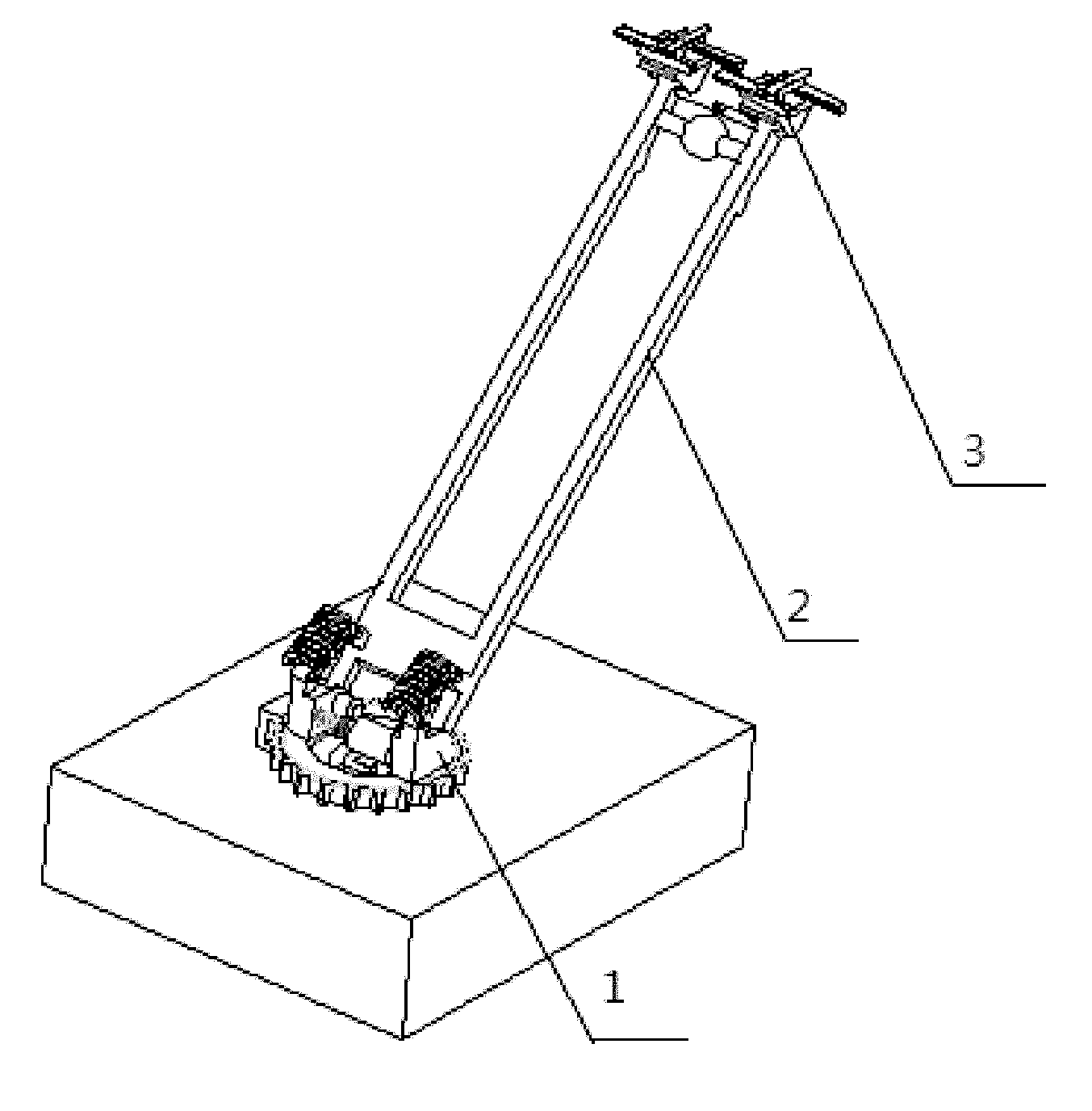
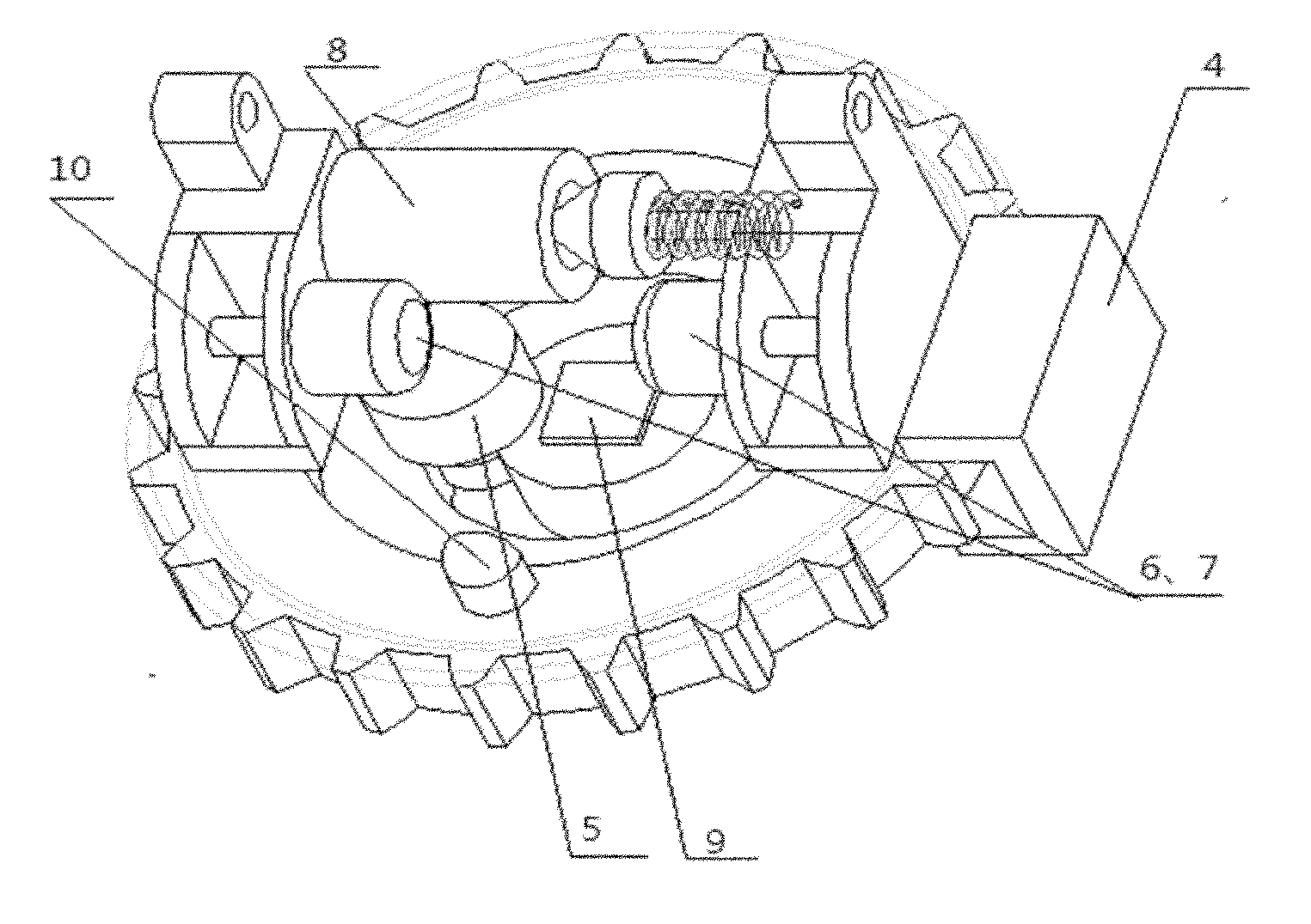
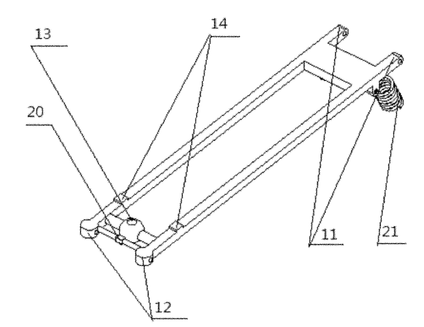
[0040] Specific implementation mode 1. Combination Figure 1 to Figure 4 To illustrate the implementation mode, the intelligent pantograph device for a trolley bus includes a pantograph assembly, a pantograph assembly and a clamp assembly 3, one end of the pantograph assembly is installed on the roof, and the other end of the pantograph assembly is connected to the pantograph assembly. One end of the pantograph assembly is hinged, and the other end of the bow frame assembly is hinged with the clamp assembly 3; the bow base assembly includes a circular bow base body 1, a pantograph rotating motor 5, a pantograph position sensor 4, and a first pantograph lifting motor 6 , the second pantograph lifting motor 7, the camera 10, the main circuit breaker 8 and the central controller 9; the first pantograph lifting motor 6 and the second pantograph lifting motor 7 are installed symmetrically on the circular bow base body 1 On the boss used to articulate the pantograph assembly, the pa...

specific Embodiment approach 2

[0048] Specific embodiment two, combine Figure 5 to Figure 8 Describe this embodiment, the application method of trolley bus intelligent pantograph, this method is realized by the following steps:

[0049] Step 1. After the trolley bus enters the electrified section, the driver uses the left and right adjustment buttons to adjust the position of the pantograph according to the image obtained by the camera 10, so that the contact line is located within the lens range of the infrared camera 20, and starts the bow raising procedure;

[0050] The specific process of the bow raising program is: disconnect the main circuit breaker 8, separate the movable line clamp 16, call the contact line tracking program to locate the position of the contact line, control the bow base rotation motor 5 to move the bow head of the pantograph directly below the contact line Nearby, this position can ensure that the contact line is embedded in the middle of the separated movable wire clip after the ...


PUM


Abstract

The invention relates to an intelligent pantograph device for trolley bus and a using method thereof, which relate to the field of intelligent control of pantograph of a trolley bus and solve the problem that the conventional trolley bus can only realize overtaking on a single side and the problem that the automatic connection cannot be realized between the pantograph and a contact wire in an overtaking process. In the invention, when the pantograph is lifted, a contact wire tracing program based on the processing of image captured by an infrared camera on a pantograph assembly is adopted to regulate the angle of the pantograph, a movable cable clamp is used to compensate for an error, and thus, the pantograph is connected to the contact wire automatically; during overtaking, a rear vehicle informs a front vehicle of lowering the pantograph through a communication unit and determines if to allow the pantograph of the front vehicle to return, the contact wire tracking program is used to lower the pantograph of the front vehicle if the pantograph of the front vehicle does not return, and the head of the pantograph is allowed to return to the edge above the vehicle body; and when the pantograph is lowered, the pantograph can fall and return automatically. The device can realize the automation of the power connection and disconnection of the trolley bus and the automation of overtaking, and greatly improve the operation efficiency and flexibility of the trolley bus. Thus, the device has certain practical value.

Description

technical field [0001] The invention relates to the field of intelligent control of trolley bus pantographs. Specifically relates to an electromechanical integrated device capable of controlling a trolleybus pantograph to automatically search for a contact line to realize trolleybus overtaking. Background technique [0002] The trolley bus has many advantages such as zero emission, high efficiency, high horsepower, and low noise. However, it can only drive in a narrow range below the contact line, and has poor flexibility and cannot overtake. After the pantograph of the trolleybus is lowered, it needs to be manually connected to the contact line, which is time-consuming and laborious, which limits its wide application. [0003] At present, the devices that solve the problem of automatic trolleybus bow raising in society all need to be aligned directly or indirectly by people, which not only reduces the efficiency of pantograph bow raising, but also distracts the driver's en...

Claims


Application Information

Patent Timeline
Patent Type & Authority Applications(China)
IPC IPC(8): B60L5/18B60L5/28
CPCY02T90/16
Inventor 王登峰叶翔张明新
Owner JILIN UNIV
Why Eureka
Try Eureka