

Fused design method for turbine machinery blades and end wall
A technology of impeller machinery and design method, which is applied in mechanical equipment, machine/engine, liquid fuel engine, etc., can solve the problem that the corner configuration method considering the intersection of blade E and end wall F has not been formed, so as to improve load capacity, The effect of improving aerodynamic performance and reducing flow loss
Inactive Publication Date: 2011-06-15
BEIJING INSTITUTE OF TECHNOLOGYGY
View PDF3 Cites 2 Cited by
- Summary
- Abstract
- Description
- Claims
- Application Information
AI Technical Summary
Problems solved by technology
The geometric configuration of the junction corner of the blade E and the end wall F plays an important role in the flow organization and separation suppression in the corner area, but the current turbine design technology has not considered this point, and has not yet formed a configuration that considers the junction corner of the blade E and the end wall F method
Method used
View moreImage
Smart ImageViewing Examples



Examples
Embodiment Construction
Login to View More PUM
 Abstract
The invention relates to a fused design method for turbine machinery blades and an end wall, and belongs to the technical field of impeller machinery. The method comprises the following steps of: determining the distribution regularities of minimum curvature radius of connecting curves and radial inclination angle of an end wall surface along the flow direction by fitting or interpolating according to the minimum curvature radius of the connecting curves of the blades at a plurality of positions and the end wall and the radial inclination angle of the end wall surface, selecting enough sections along the flow direction, performing smooth connection on the blades and the end wall in the sections in a form of the blade and end wall connecting curves in the determined end region, and enveloping the formed curve family into a blade-end wall fused surface so as to complete the fusion of the blades and the end wall. The method improves the load capacity of a turbine, achieves the purposes of separating a turbine machinery inhibiting angle region and reducing the flow loss, and can organize the angular region flow more effectively at the turbine machinery design stage and promote the pneumatic performance of the turbine; and the method is not only suitable for the turbine blades, but also suitable for the fusion of airplane wings and fuselage.
Description
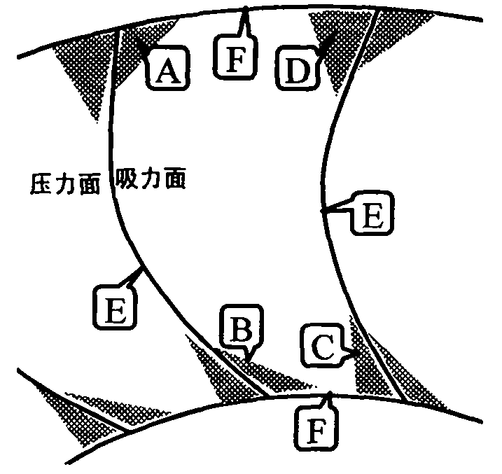
A fusion design method of blade and end wall of turbomachinery technical field The invention relates to a fusion design method of blades and end walls of a turbomachinery, belonging to the technical field of turbomachinery. Background technique In the turbomachine, in the quasi-orthogonal plane (S3 flow plane) orthogonal to the intended flow direction, four junction corners A, B, C and D are formed by the intersection of blade E and end wall F, as shown in Figure 1. Its flow is mainly characterized by the intersection of the leaf surface boundary layer and the end wall boundary layer, especially in the two corners A and B formed by the blade suction surface and the end wall, where there are not only the leaf surface suction surface boundary layer and the The boundary layer of the end wall, as well as the secondary flow driven by the pressure difference between the pressure side and the suction side and blocked by the end wall, often separates. Once separation occurs, the ...
Claims
Login to View More Application Information
Patent Timeline
 Patent Type & Authority Applications(China)
IPC IPC(8): F04D29/38F04D29/52
Inventor 季路成伊卫林田勇刘艳明
Owner BEIJING INSTITUTE OF TECHNOLOGYGY