Light homogenizer and application of optical fiber panel

A technology of optical fiber panels and homogenizers, which is applied to semiconductor devices, instruments, optics, etc. of light-emitting elements, and can solve the difficulty of coupling the input end with LEDs/IREDs, and there is no homogenization plate in the near-infrared band, and small compound glasses. The lens is small and other issues, to achieve the effect of light weight, low power consumption, and easy beam shape

Inactive Publication Date: 2011-06-15
李金宗
View PDF0 Cites 5 Cited by
  • Summary
  • Abstract
  • Description
  • Claims
  • Application Information

AI Technical Summary

Problems solved by technology

[0006] 2. The solution of using Fresnel lenses and compound glasses: the small lens of the compound glasses cannot be made small enough, the light uniformity is limited, it cannot meet the requirements, and the volume is relatively large
[0007] 3. The solution based on the particle light guide plate: the particle light guide plate is also called uniform light plate, which can be used in the visible lig

Method used


Image

  • Light homogenizer and application of optical fiber panel
  • Light homogenizer and application of optical fiber panel
  • Light homogenizer and application of optical fiber panel

Examples


Embodiment 1

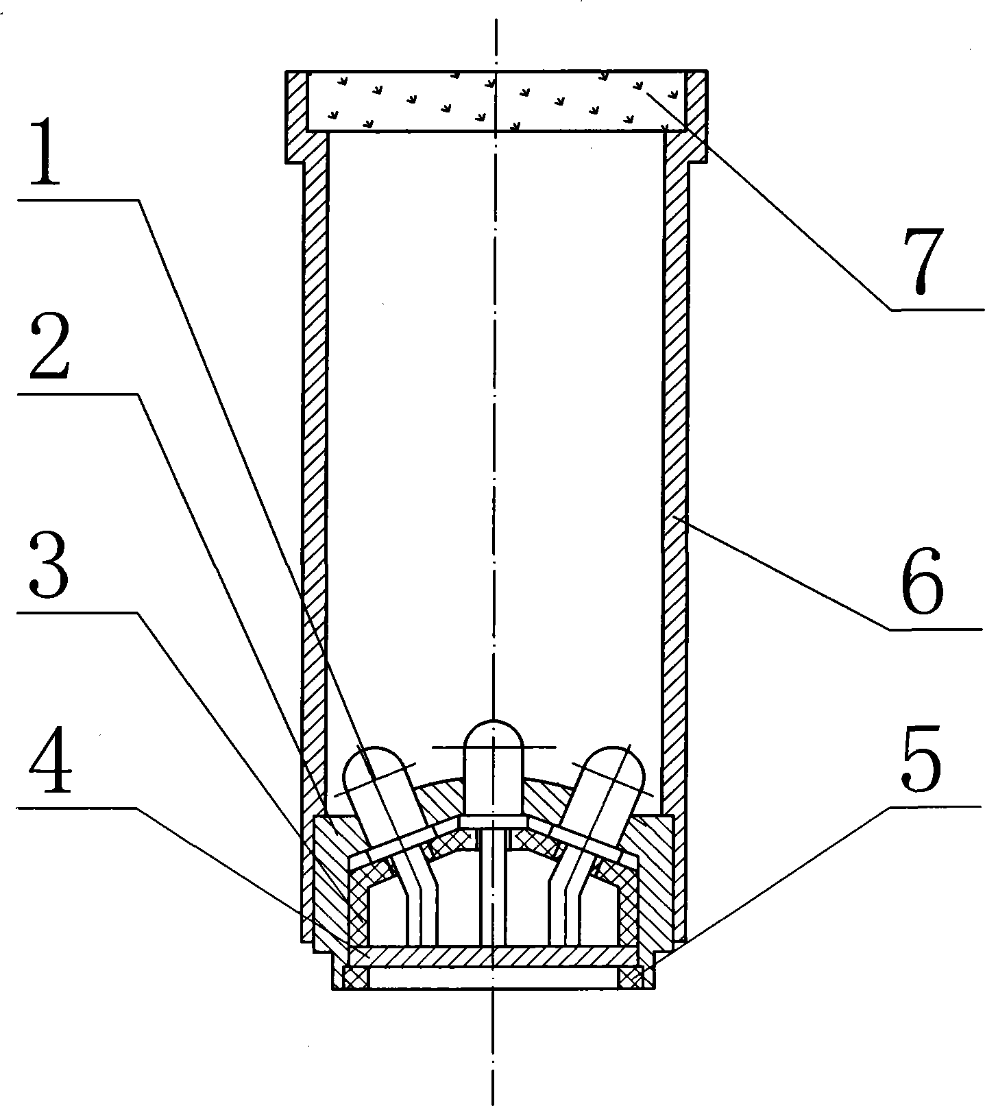
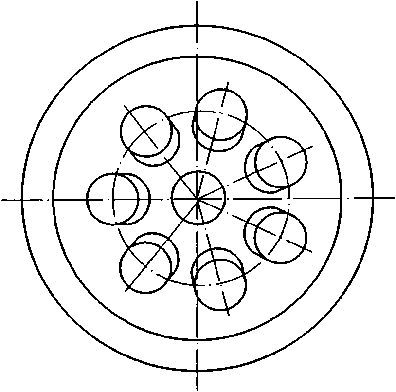
[0046] The homogenizer comprises: a cylindrical housing 6, one end of the cylindrical housing is equipped with a high-uniformity optical fiber panel 7, and the other end is equipped with a light-emitting combination, and the light-emitting combination includes a circuit board 4 and a Group light emitting device 1. The light emitting device is a light emitting diode.

[0047] A kind of This product is a special case of the application of the fiber optic panel in realizing the transformation from the point light source to the extended surface light source, and the fiber optic panel can also be applied to other purposes.

Embodiment 2

[0049] In the light homogenizer mentioned above, there is an LED skeleton 2 between the light emitting devices, an LED support frame 3 under the LED skeleton, and a retaining ring 5 on the periphery of the circuit board.

[0050] The light-emitting device is a near-infrared light-emitting diode.

[0051] Original feature requirements:

[0052] Under the condition that a group of IREDs is used in the light-emitting combination and the derating of category I is satisfied, the main optoelectronic characteristics are as follows:

[0053] (1) Forward current IF: I F =120~140mA;

[0054] (2) Forward voltage V F :V F =2.2~2.6V (measured on the circuit board);

[0055] (3) Peak wavelength λ p : λ p = λ p 0 + Δ λ p |Δλ p |≤2nm;

[0056] (4) Spectral line width Δλ 0.5 : Δλ 0.5 ≤52nm;

[0057] (5) Radiation beam characteristics...


PUM


Abstract

The invention relates to a light homogenizer and application of an optical fiber panel. Due to the adoption of a charge coupled device (CCD) camera of which the focal length is more than or equal to 16 millimeters, the petal phenomenon is likely to occur after an image is formed within close range by a near-field marker, and the uniformity cannot meet the requirement. In order to solve the problems of petals and particularly the near-field marker, the light homogenizer is arranged additionally on the basis of the original design. The light homogenizer comprises a cylindrical shell (6), wherein a high-uniformity optical fiber panel (7) is arranged at one end of the cylindrical shell, and a luminous combination is arranged at the other end of the cylindrical shell; and the luminous combination comprises a circuit board (4) and a group of luminous devices (1). The light homogenizer is an important facility for solving the problem of uniformity in the near-field marker.

Description

Technical field: [0001] The invention relates to a uniform light device for an active optical (target) mark. Background technique: [0002] An active optical (target) marker, in order to have the advantages of small size, light weight and low power consumption, while ensuring high reliability, long life, and meeting the requirements of large radiation power, the light source of the marker is preferably several or several It consists of ten LEDs / IREDs, but each of them is a point light source. The spatial distribution of the radiant light intensity of such a marker is not uniform, and in the application as a cooperative target of a CCD optical imaging sensor, petals will appear after imaging in a relatively short range. Although the near-field petal problem of the marker is related to the focal length of the camera, the most fundamental reason is that the light source of the marker is composed of several or dozens of point light sources, and there must be a certain distance ...

Claims


Application Information

Patent Timeline
IPC IPC(8): F21S2/00F21V8/00F21V23/00F21V19/00F21Y101/02F21K9/20F21K9/61F21Y115/10
Inventor 李金宗李冬冬朱兵马冬冬朱福珍
Owner 李金宗
Why Eureka
Try Eureka