Contact finger

A technology of contact fingers and contact pieces, which is applied in the direction of contacts, contact surface shape/structure, electrical components, etc., can solve problems such as increased line loss, increased heat generation, and contact surface wear, and achieves high conductivity reliability, Simple finger structure and long service life

Inactive Publication Date: 2011-06-15
BEIJING VEE ELECTRIC CO LLTD
View PDF6 Cites 4 Cited by
  • Summary
  • Abstract
  • Description
  • Claims
  • Application Information

AI Technical Summary

Problems solved by technology

[0003] Under modern technology, the static contacts in high-voltage switchgear generally use coil springs to elastically fix the contact fingers made of copper die-casting, and install them in the static contact seat, and the moving contacts are fixed by the impact force during operation. The conductive function is realized after the contact fingers are fully contacted. This requires that the elasticity of the coil spring must be good, the material selection and processing accuracy must be guaranteed, and the contact piece must be very uniform and the concentricity must be good when fixed, which makes it difficult for traditional process equipment to achieve. , resulting in long-term operation and wear of the contact surface of the moving and static contacts, resulting in increased resistance and increased heat generation, which reduces the service life of the switchgear and increases line loss

Method used


Image

  • Contact finger
  • Contact finger

Examples


Embodiment Construction

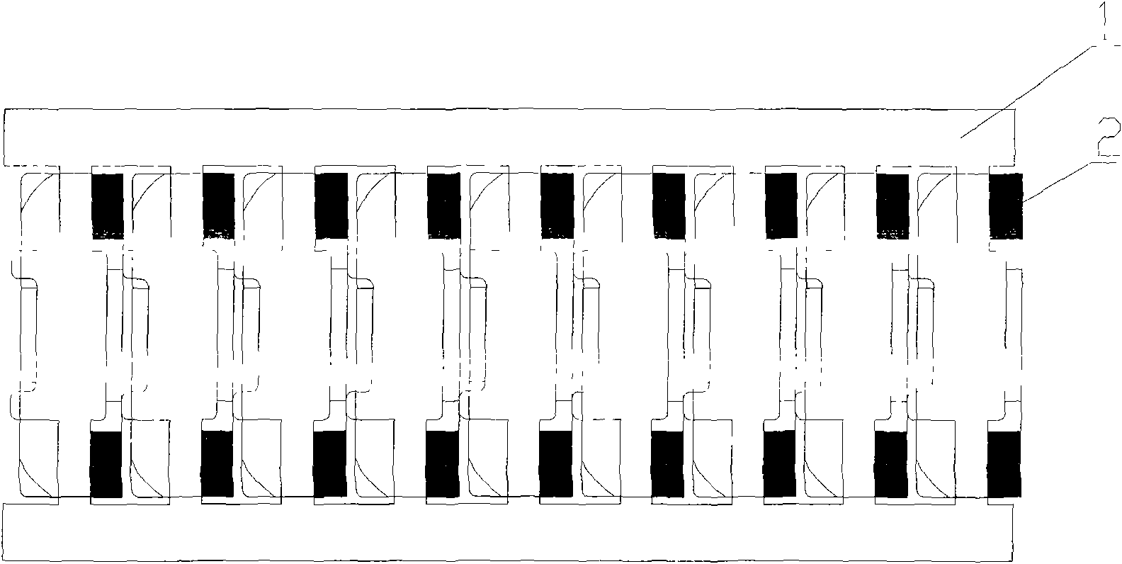
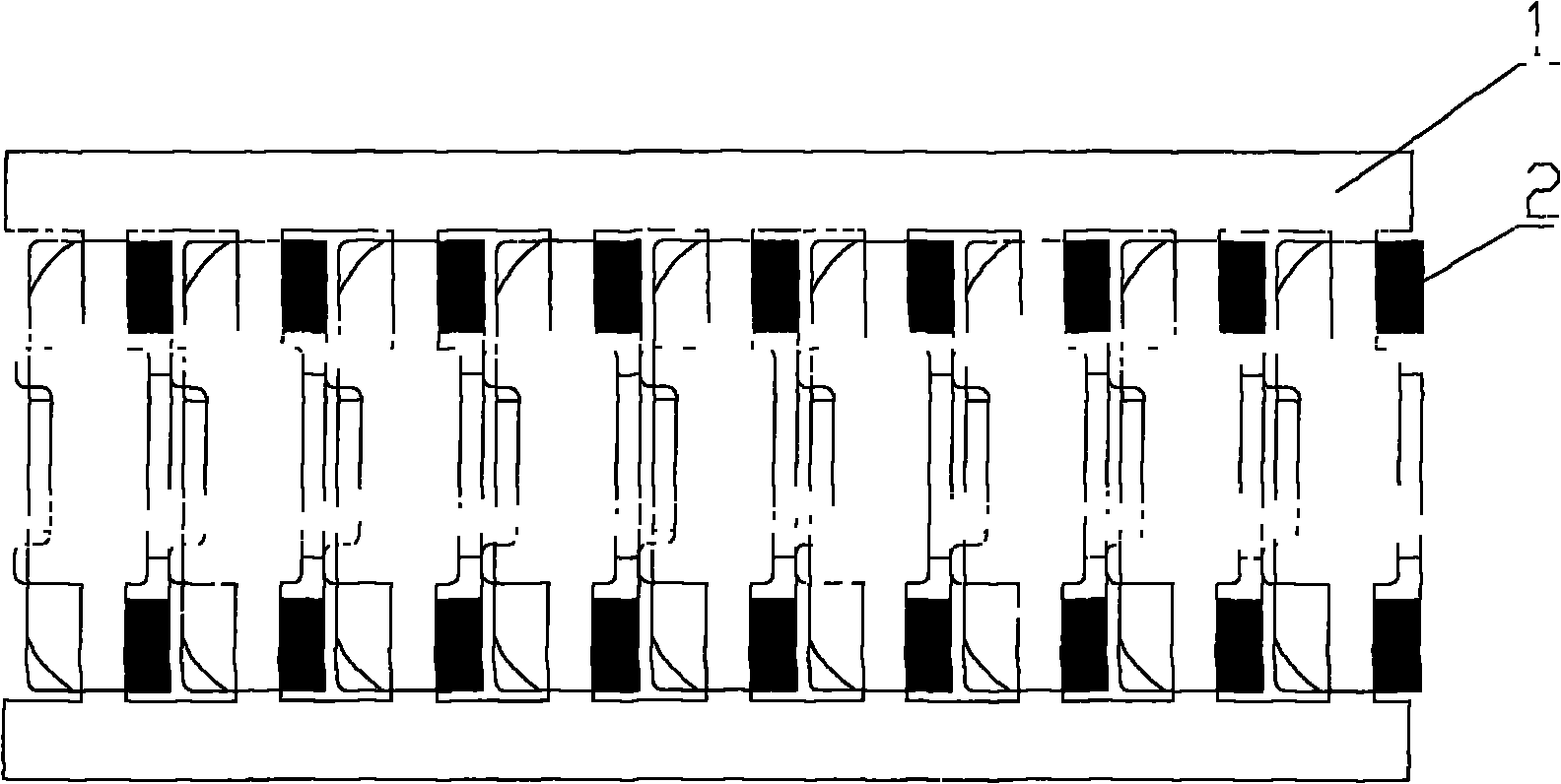
[0013] Below, refer to the attached figure 1 Preferred embodiments of the present invention will be described in detail. What needs to be explained before this is that the terms or words used in this specification and claims should not be limitedly interpreted as the usual meaning or the meaning in the dictionary, but should be based on the best way for the inventor to explain the term. The principle of properly defining the concepts is interpreted as meanings and concepts consistent with the technical idea of ​​the present invention. Subsequently, the embodiment described in this description and the structure shown in the drawings are only one of the best embodiments of the present invention, and cannot fully represent the technical ideas of the present invention, so it should be understood that there may be possible Various equivalents and modifications are substituted.

[0014] Such as figure 1 As shown, the present invention is made up of two parts of spring steel band ...


PUM


Abstract

The invention relates to a contact finger for a fixed contact in an on/off circuit or a bus connecting device of a high-voltage switch equipment, wherein the high-voltage switch equipment relates to a circuit breaker, a load switch and a disconnecting switch. The contact finger is used for electric conduction contact between a moving contact and a fixed contact, has the advantages of small size, large contact area and good electric conductivity, and is also suitable for two occasions including static connection and sliding connection between the moving contact and the fixed contact.

Description

Technical field [0001] The invention relates to a contact finger for a static contact in a high-voltage switchgear or a high-voltage switchgear bus connection device, and the high-voltage switchgear refers to a circuit breaker, a load switch, and a disconnector. Background technique [0002] High-voltage switchgear is usually used to connect and disconnect power transmission and distribution circuits under no-load, normal load or short-circuit conditions. The power on and off of high-voltage switchgear is mainly realized by the effective connection between moving contacts and static contacts. [0003] Under modern technology, the static contacts in high-voltage switchgear generally use coil springs to elastically fix the contact fingers made of copper die-casting, and install them in the static contact seat, and the moving contacts are fixed by the impact force during operation. The conductive function is realized after the contact fingers are fully contacted. This requires ...

Claims


Application Information

Patent Timeline
Patent Type & Authority Applications(China)
IPC IPC(8): H01H1/06H01H1/50
Inventor 钱璿翟鹏飞赵海花
Owner BEIJING VEE ELECTRIC CO LLTD
Why Eureka
Try Eureka