Drive control circuit for shunt-wound synchronous rectification tubes and switching power supply
A technology for driving control circuits and synchronous rectifier tubes, applied in electrical components, output power conversion devices, etc., can solve the problems of large driving loss, inability to optimize efficiency, low efficiency, etc., to improve light-load efficiency and reduce driving loss. Effect
Active Publication Date: 2011-06-15
HUAWEI DIGITAL POWER TECH CO LTD
View PDF2 Cites 18 Cited by
- Summary
- Abstract
- Description
- Claims
- Application Information
AI Technical Summary
Problems solved by technology
Therefore, switching power supplies have large driving losses and low efficiency in application scenarios with small loads, and cannot achieve efficiency optimization for load conditions.
Method used
View moreImage
Smart ImageViewing Examples
Examples
Embodiment Construction
Login to View More PUM
 Abstract
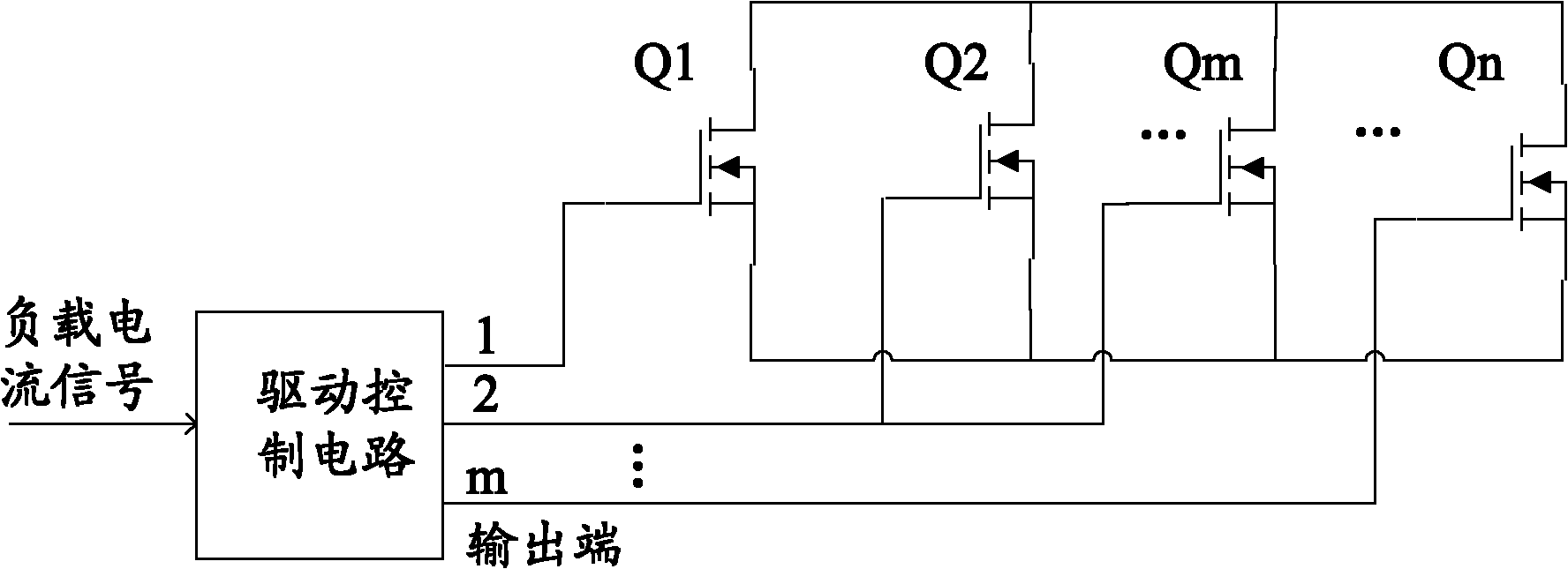
The invention discloses a drive control circuit for shunt-wound synchronous rectification tubes, which is used for driving and controlling the N shunt-wound synchronous rectification tubes, wherein N is a positive integer. The drive control circuit has an input end and M output ends, wherein the input end is used for acquiring a load current signal; the M output ends are used for outputting driving signals; M is the positive integer more than or equal to N; the M output ends are connected with drive electrodes of the N synchronous rectification tubes; the drive electrode of each synchronous rectification tube is connected with one output end; each output end is connected with the drive electrode of at least one synchronous rectification tube; and the drive control circuit controls the number of switched-on synchronous rectification tubes of the N shunt-wound synchronous rectification tubes according to the magnitude of the load current signal. The embodiment of the invention also provides a corresponding switching power supply. The drive control circuit provided by the embodiment of the invention can adaptively adjust the number of the switched-on synchronous rectification tubes according to the change of a load, thereby satisfying application needs, reducing the drive loss under low-load condition and improve light load efficiency.
Description
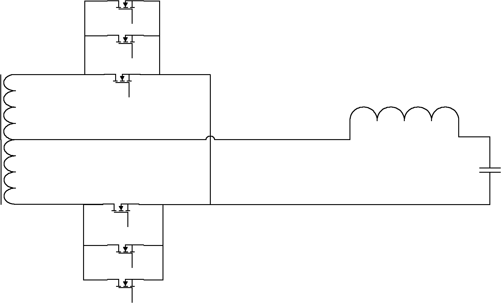
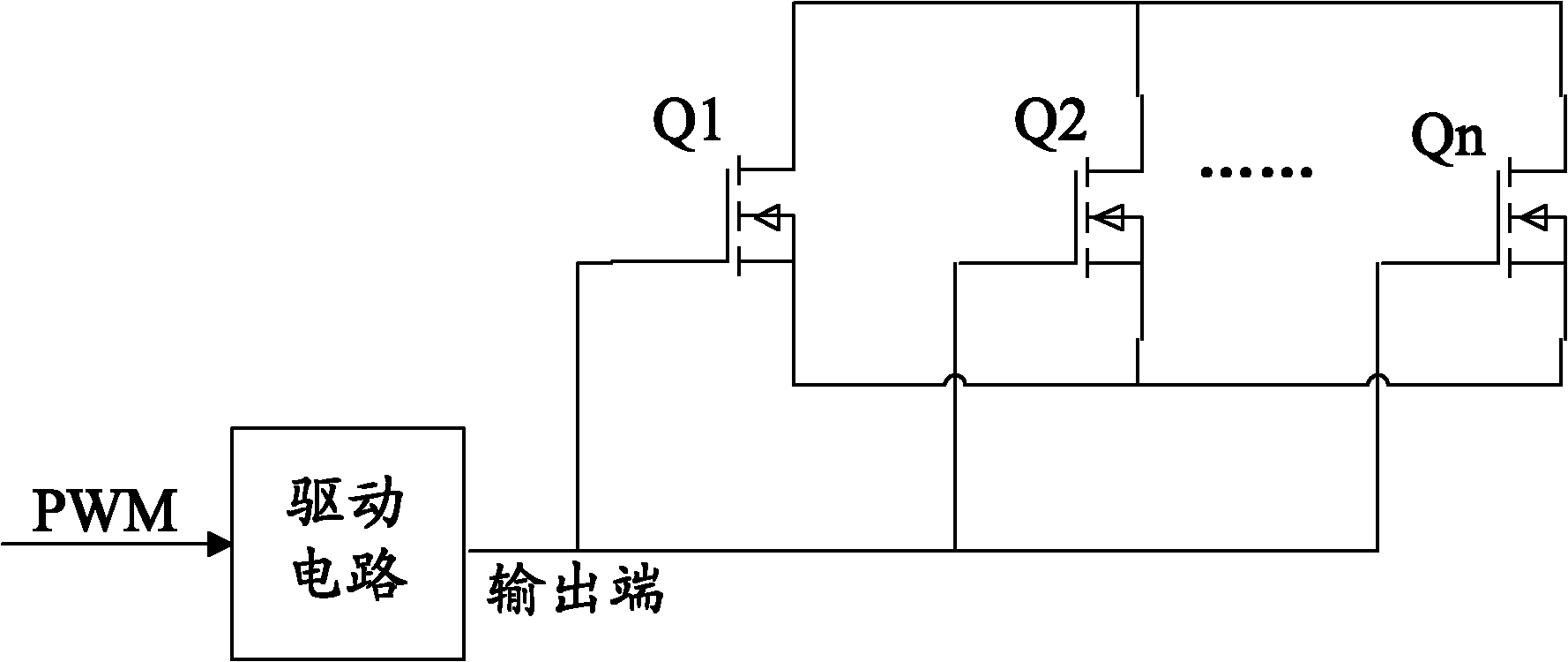
A parallel synchronous rectifier driving control circuit and switching power supply technical field The invention relates to the technical field of synchronous rectification, in particular to a drive control circuit and a switching power supply of parallel synchronous rectification tubes. Background technique Synchronous rectification (Synchronous Rectification, SR) technology is widely used in switching power supplies to improve the efficiency of switching power supplies. The synchronous rectification technology uses a special power metal oxide semiconductor field effect transistor (MetalOxideSemiconductorFieldEffectTransistor, MOSFET) with extremely low on-state resistance as a synchronous rectifier tube to replace the rectifier diode to reduce the rectification conduction loss. In order to meet the application scenarios of high power and high current and reduce losses, the application of synchronous rectifier tubes in parallel has appeared. Figure 1 is a schematic diag...
Claims
Login to View More Application Information
Patent Timeline
 Patent Type & Authority Applications(China)
IPC IPC(8): H02M1/088
Inventor 周涛
Owner HUAWEI DIGITAL POWER TECH CO LTD
Features
- R&D
- Intellectual Property
- Life Sciences
- Materials
- Tech Scout
- Unparalleled Data Quality
- Higher Quality Content
- 60% Fewer Hallucinations
Learn More Browse by: Latest US Patents, China's latest patents, Technical Efficacy Thesaurus, Application Domain, Technology Topic, Popular Technical Reports.
© 2025 PatSnap. All rights reserved.Legal|Privacy policy|Modern Slavery Act Transparency Statement|Sitemap|About US| Contact US: help@patsnap.com


