

High power factor constant current light-emitting diode (LED) lighting circuit
A technology of LED lighting and high power factor, applied in lighting devices, electric lamp circuit layout, electric light source, etc., can solve the problem of inability to cut off the channel current, and achieve the effect of simple structure, few components, and avoidance of burning
Inactive Publication Date: 2011-06-15
NANKER GUANGZHOU SEMICON MFG
View PDF3 Cites 11 Cited by
- Summary
- Abstract
- Description
- Claims
- Application Information
AI Technical Summary
Problems solved by technology
When a negative voltage is applied between the gate and the source, the channel can be cut off, and the conduction current is zero. The gate voltage at this time is defined as the turn-on voltage, but if the channel concentration is too thick and the depth is too deep, the gate Pole will not be able to intercept the channel current
The depletion-type MOS transistor is not as convenient as the enhancement-type MOS transistor in logic application because the drain-source current is turned on at a constant current when the gate and source voltages are zero, so it has not been isolated by the industry. Make a device to use
Method used
View moreImage
Smart ImageViewing Examples

Examples
Embodiment 1
Embodiment 2
Embodiment 3
Login to View More PUM
 Abstract
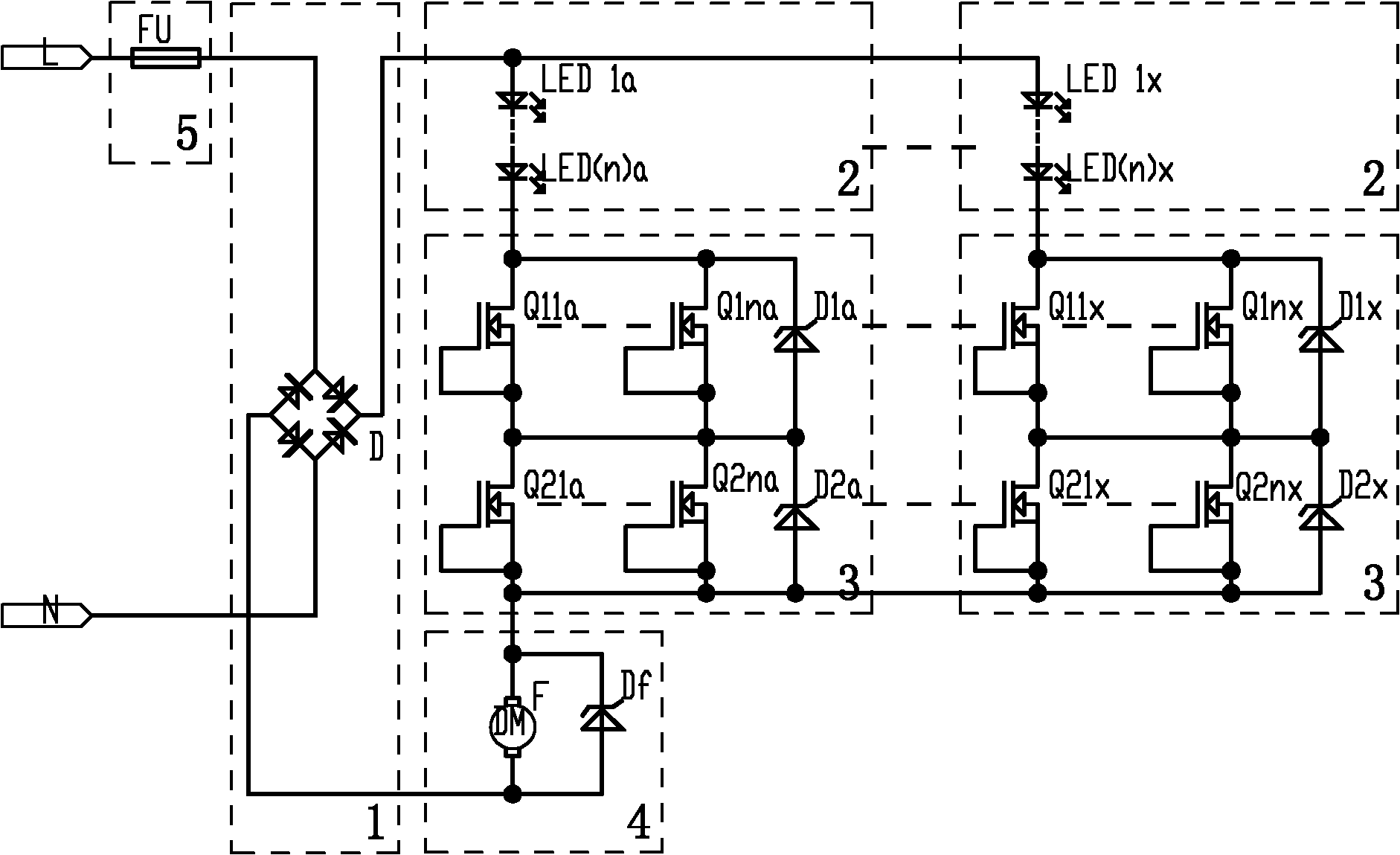
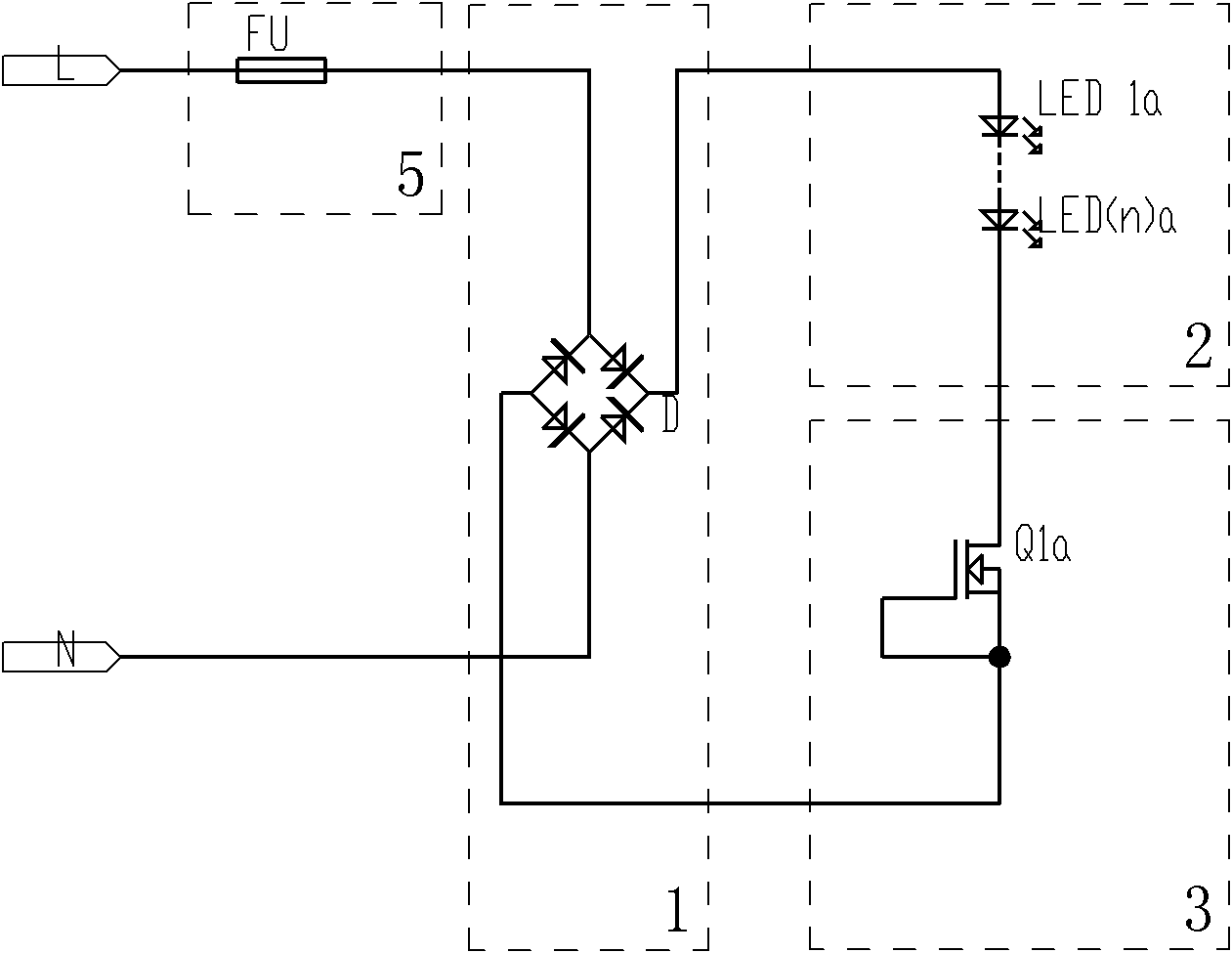
The invention discloses a high power factor constant current light-emitting diode (LED) lighting circuit with a simple structure, a few components and a long LED service life. The high power factor constant current light-emitting diode (LED) lighting circuit comprises a rectifier circuit (1), an LED light source load (2), and a constant current source circuit (3). The high power factor constant current LED lighting circuit does not include a filter capacitor. An alternating current is rectified by the rectifier circuit (1) and then converted into a pulsating direct current. The pulsating direct current forms a loop through the LED light source load (2) and the constant current source circuit (3). The constant current source circuit (3) performs voltage regulation and current stabilization of the LED light source load (2). An LED light source load (4) comprises at least one group of a plurality of LEDs which are connected in series. A constant current source circuit (6) comprises at least one group of constant current source devices. Each group of constant current source devices comprises at least one depletion mode field effect transistor. The drain of the depletion mode field effect transistor is a contact. The source and the grid of the depletion mode field effect transistor are in short connection and form another contact. The high power factor constant current LED lighting circuit can be widely applied in field of LED lighting circuit.
Description
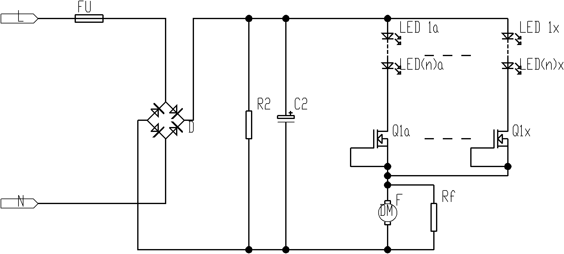
High power factor constant current LED lighting circuit technical field The invention relates to a high power factor constant current LED lighting circuit. Background technique At present, the application of LEDs is becoming more and more extensive, and LED lamps for daily indoor and outdoor lighting are also becoming more and more popular. Current LED lighting AC drive circuits are generally equipped with filter circuits to avoid voltage fluctuations. As shown in Figure 1, the simplest filter circuit generally includes at least one filter capacitor C2 and one bleeder resistor R2, and complex filter circuits may Including more capacitors, due to the existence of capacitors and the large value of filter capacitance, the proportion of reactive power in the circuit is relatively large, causing the power factor of the entire circuit to be very low, even lower than 0.5, which does not meet the requirements of some countries. technical standards or specifications. In order to ...
Claims
Login to View More Application Information
Patent Timeline
 Patent Type & AuthorityApplications(China)
IPC IPC(8): H05B37/02H02H3/08
CPCY02B20/347H02H3/08H05B37/02H05B33/0818H05B45/345H05B45/37Y02B20/30
Inventor吴俊纬
OwnerNANKER GUANGZHOU SEMICON MFG