Hydraulic buffer system

A hydraulic buffer and hydraulic cylinder technology, applied in the direction of liquid shock absorbers, springs, shock absorbers, etc., can solve problems such as oil leakage, large space occupation, property loss, etc., achieve reduced manufacturing costs, simple pressure control, and improved competitiveness force effect

Active Publication Date: 2012-07-25
JOINTECH (SUZHOU) VEHICLE SYST CO LTD
View PDF1 Cites 0 Cited by
  • Summary
  • Abstract
  • Description
  • Claims
  • Application Information

AI Technical Summary

Problems solved by technology

Articulated buses are generally composed of front and rear compartments and a chassis hinge system connecting the front and rear compartments. The hydraulic buffer system in the chassis hinge system is a key factor restricting the performance of the articulated bus. In the prior art, the hydraulic buffer system of an articulated bus generally consists of two hydraulic Cylinder, a hydraulic controller and an electrical control system. The hydraulic cylinder is controlled by the hydraulic controller to change the size of its output resistance. The electrical control system sends a signal to the hydraulic controller according to the turning angle of the vehicle to change different pressure values, such as Chinese patent CN201086607 discloses a hydraulic control system that controls the hydraulic damping through the rotation of the mandrel, thereby changing the hydraulic control system of the buffer damping. Although this control system can form different damping according to the change of the included angle of the vehicle, it can prevent the front and rear vehicles from shearing. However, the structure of the mandrel is complex, the machining accuracy is high, the cost is high, the installation and connection are complicated, the space is large, and there are also disadvantages such as oil leakage, spool stuck or electrical system failure.
[0003] At the same time, because the buffer damping in the prior art cannot be accurately controlled, drivers often have accidents due to the large turning angle when driving an articulated vehicle, especially when making a large turn, causing casualties and property losses

Method used


Image

  • Hydraulic buffer system
  • Hydraulic buffer system
  • Hydraulic buffer system

Examples


Embodiment Construction

[0022] In order to understand the technical content of the present invention more clearly, the following examples are given in detail.

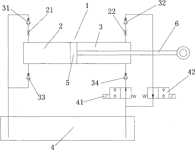
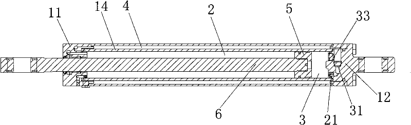
[0023] Such as figure 1 - As shown in Figure 5, the present invention relates to a hydraulic buffer system, including: three chambers (including buffer chamber 2, lock chamber 3 and oil storage tank 4), two controls (including first solenoid valve 41 and second solenoid valve 42 ), two hydraulic dampers (the first hydraulic damper 21 and the second hydraulic damper 22), four one-way valves and the cylinder liner 14, piston 5, piston rod 6, sealing ring, etc. that conventional hydraulic cylinders have. The piston 5 is slidably arranged in the hydraulic cylinder 1, and divides the hydraulic cylinder into a buffer chamber 2 and a locking chamber 3, and the piston 5 and the piston rod 6 are fixedly connected;

[0024] The buffer chamber 2 is connected in series with the first hydraulic damper 21, the first one-way valve 31 and the oil storage ta...


PUM


Abstract

The invention relates to a hydraulic buffer system, which comprises a hydraulic cylinder, an oil storage tank, a first one-way valve, a second one-way valve, a third one-way valve, a forth one-way valve, a first hydraulic damper, a second hydraulic damper, a first electromagnetic valve and a second electromagnetic valve, wherein the hydraulic cylinder comprises a cylinder sleeve, a piston and a piston rod; the piston slides in the cylinder sleeve; and the hydraulic cylinder is divided into a buffer cavity and a locking cavity through the piston. The system has an ingenious design, a simple and compact structure, low production cost and a good buffering effect and is convenient to maintain when used on a vehicle; an oil discharge circuit is provided with a constant-value hydraulic damper, so that a resistance buffering effect which is proportional to the corner velocity of the vehicle is achieved; and the on-off of an oil circuit of the locking cavity is controlled through the electromagnetic valves, so that the vehicle has the functions of locking corner surpassing and recovering direct movement at the same time.

Description

technical field [0001] The invention relates to the technical field of damping and shock absorbing control systems for vehicles, in particular to a hydraulic buffer system. Background technique [0002] With the rapid development of my country's automobile manufacturing industry, various vehicle manufacturing industries are also advancing by leaps and bounds. Articulated buses are gradually popularized in large and medium-sized cities in China due to their large passenger capacity and high utilization coefficient. Articulated buses are generally composed of front and rear carriages and a chassis articulation system connecting the front and rear carriages. The hydraulic buffer system in the chassis articulation system is a key factor restricting the performance of articulated cars. In the prior art, the hydraulic buffer system of articulated buses generally consists of two hydraulic Cylinder, a hydraulic controller and an electrical control system. The hydraulic cylinder is c...

Claims


Application Information

Patent Timeline
Patent Type & Authority Patents(China)
IPC IPC(8): F16F9/19F16F9/32F16F9/56
Inventor 郝庆军
Owner JOINTECH (SUZHOU) VEHICLE SYST CO LTD
Why Eureka
Try Eureka