Passive optical network

A technology of passive optical network and optical network unit, which is applied to the selection device, electrical components, selection device and other directions of the multiplexing system to achieve a convenient number and transmission distance of optical signals, increase the number of wavelengths, and improve the uplink access bandwidth. Effect

Active Publication Date: 2011-06-22
HISENSE BROADBAND MULTIMEDIA TECH
View PDF4 Cites 6 Cited by
  • Summary
  • Abstract
  • Description
  • Claims
  • Application Information

AI Technical Summary

Problems solved by technology

[0005] The present invention aims at the above-mentioned shortcomings and deficiencies existing in the existing passive optical network using a single downlink wavelength optical signal

Method used


Image

  • Passive optical network
  • Passive optical network
  • Passive optical network

Examples


Embodiment Construction

[0019] The technical solutions of the present invention will be described in further detail below with reference to the accompanying drawings and specific embodiments.

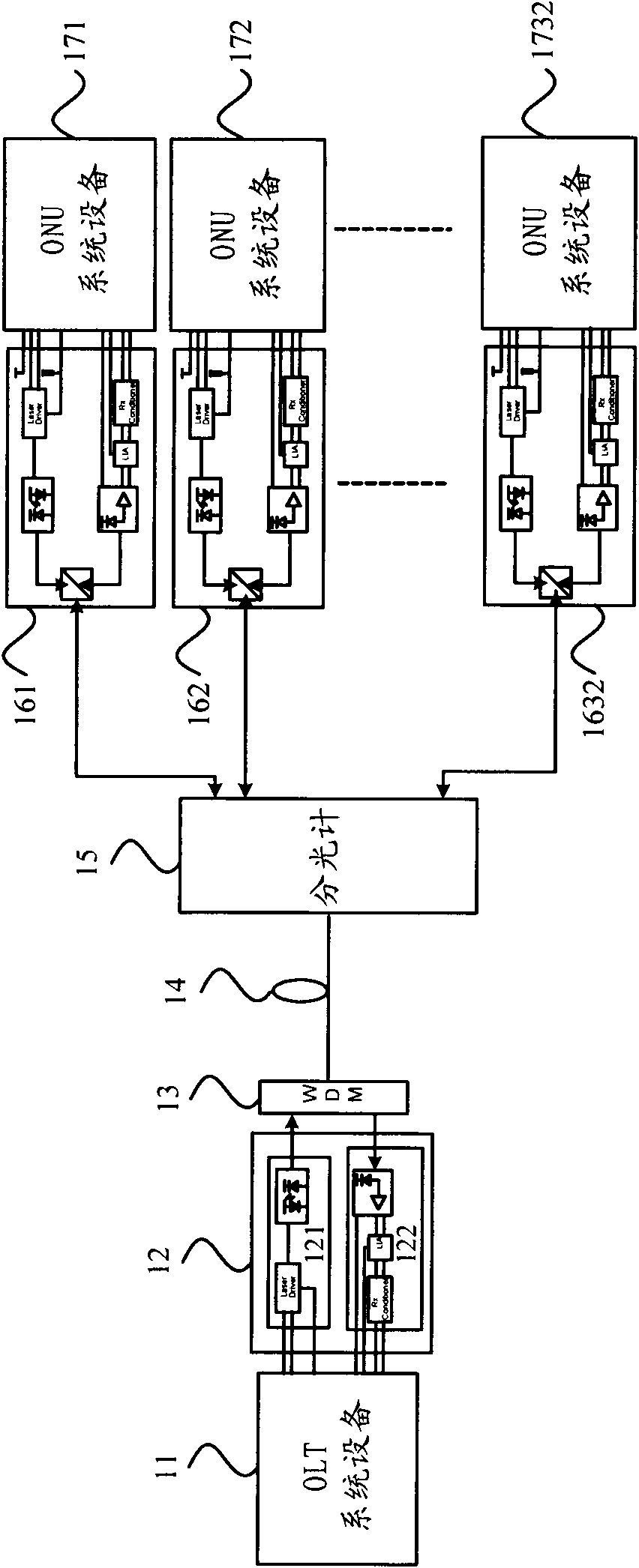
[0020] The present invention starts from the layout structure of the existing passive optical network, and considers that the existing passive optical network generally adopts an OLT to carry a plurality of ONUs through a spectrometer, and adopts a downlink optical signal of one wavelength and an uplink optical signal of one wavelength for signalling The transmission structure has shortcomings such as small ONU access bandwidth, large optical loss, and inconvenience to expand the number of ONUs. A new passive optical network is proposed, which can effectively solve the problems of existing passive optical networks.

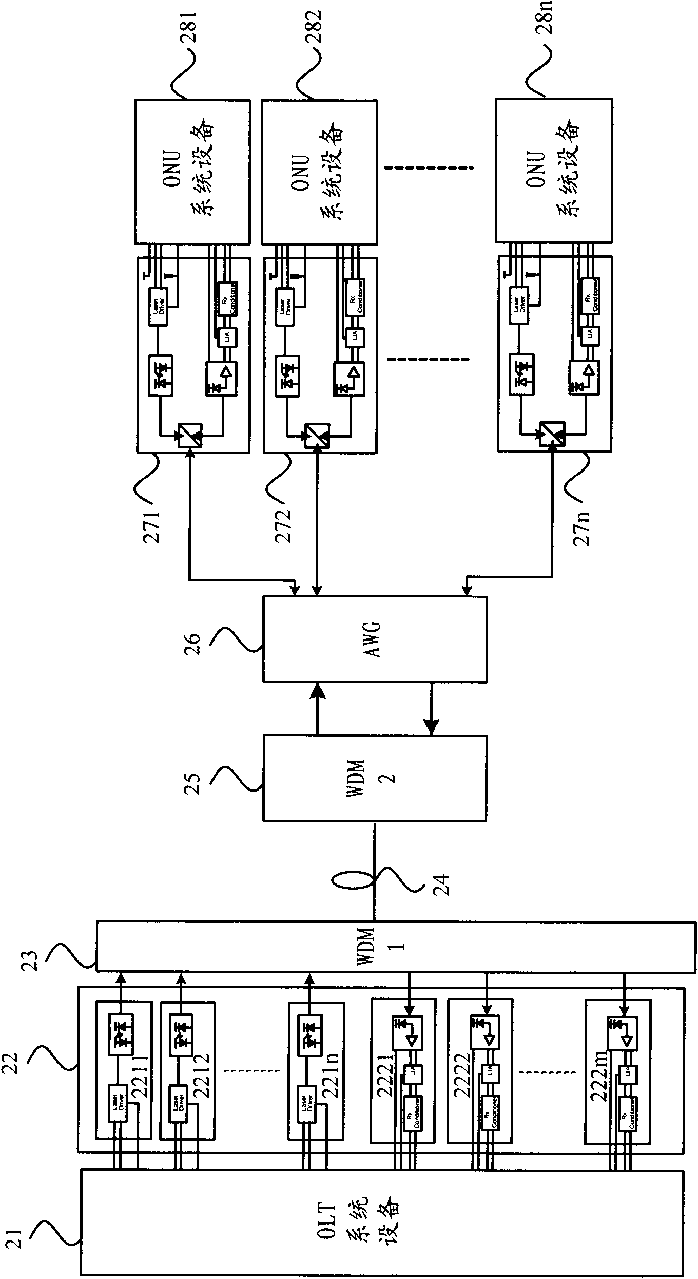
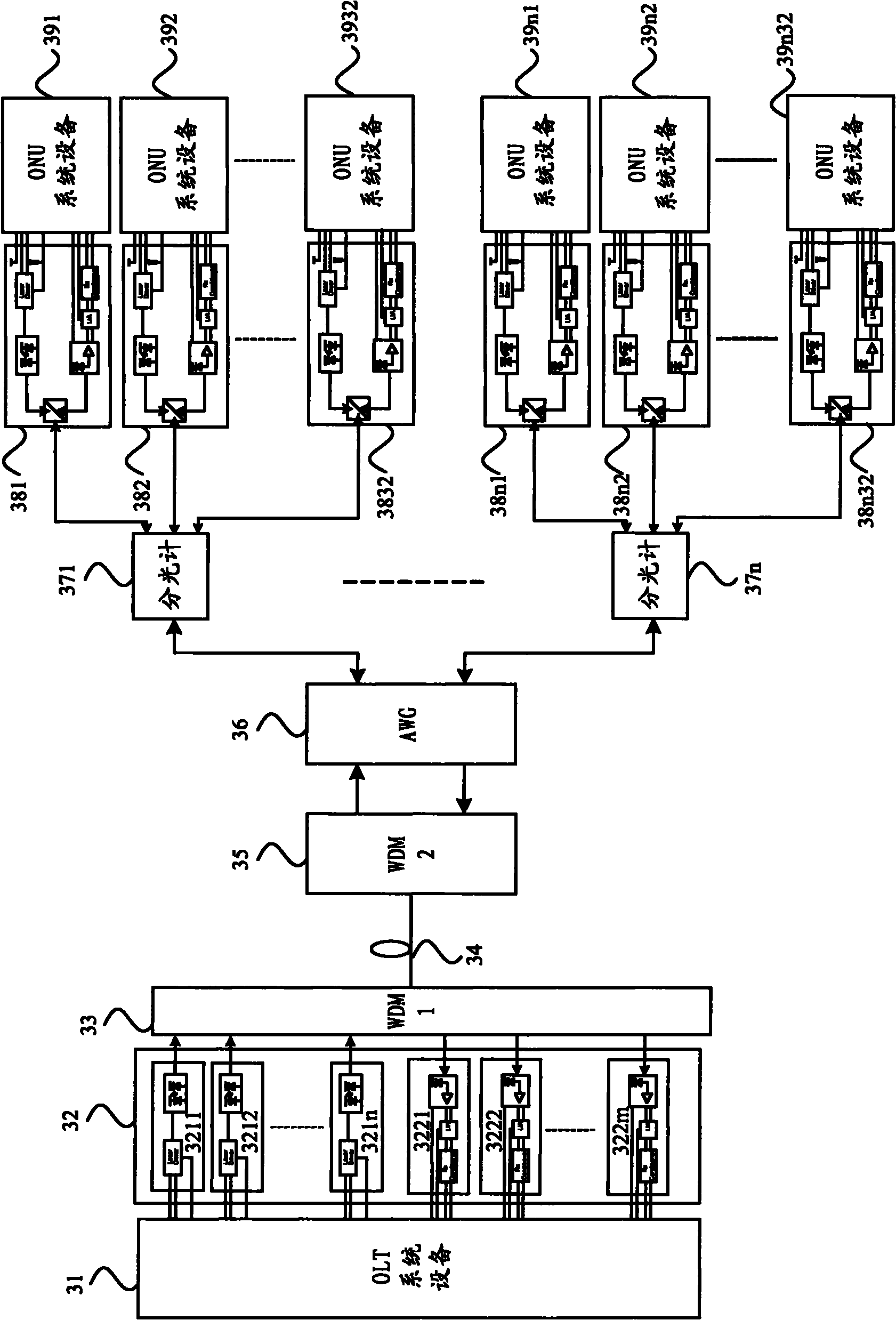
[0021] figure 2 and image 3 The schematic structural diagrams of two embodiments of the passive optical network of the present invention are respectively shown.

[0022] First refer to figur...


PUM


Abstract

The invention discloses a passive optical network, which comprises an optical line terminal, an optical cable and an optical network unit, wherein the optical line terminal comprises n transmitting light assembly units and m receiving light assembly units, and n and m are natural numbers of more than 1; and one end of the optical cable is connected with the optical line terminal, the other end of the optical cable is connected with an arrayed waveguide grating, and the arrayed waveguide grating is connected with the optical network unit. The passive optical network can realize point-to-point transmission of downlink optical signals so as to improve downlink access bandwidth of a terminal user.

Description

technical field [0001] The present invention relates to a passive optical network, in particular to a passive optical network that improves user access bandwidth, and belongs to the technical field of optical communication. Background technique [0002] At present, in the field of optical communication technology, commonly used passive optical networks include EPON (Ethernet Passive Optical Network) and GPON (Gigabit Passive Optical Network) with transmission rates of 1 Gbps and 2.5 Gbps. 10G EPON (10 Gigabit Ethernet Passive Optical Network) and XGPON (10 Gigabit Passive Optical Network) with a transmission rate of 10Gbps have also been deployed in some experimental bureaus, and have achieved success. users) deployment and use in the realm. [0003] The downlink modes of the existing passive optical networks all use the broadcast mode, and the broadcast information is distributed to several user terminals through a spectrometer. Taking XGPON as an example, its network str...

Claims


Application Information

Patent Timeline
IPC IPC(8): H04Q11/00H04J14/02
Inventor 张强赵其圣薄生伟杨思更薛登山
Owner HISENSE BROADBAND MULTIMEDIA TECH
Why Eureka
Try Eureka