Method for manufacturing carbon fiber reinforced resin matrix composite structure
A composite material and resin-based technology, which is applied in the field of preparation of carbon fiber reinforced resin-based composite material structural parts, can solve the problems of inability to use a prepreg-autoclave molding process, restrict the wide application of composite materials, and achieve good application prospects. , The effect of reducing material cost and improving interlaminar fracture toughness
- Summary
- Abstract
- Description
- Claims
- Application Information
AI Technical Summary
Problems solved by technology
Method used
Image
Examples
Embodiment 1
[0024] Carbon fiber (Toray T300-1K, Japan) is impregnated with epoxy resin (Kunshan Yubo Resin Factory, FW-77 type), and the pultrusion process (such as figure 1 As shown) to prepare carbon fibers with a diameter of 0.3mm, where the glue tank temperature is 36°C, the mold temperature is 89°C, and the pultrusion speed is 0.18m / min.
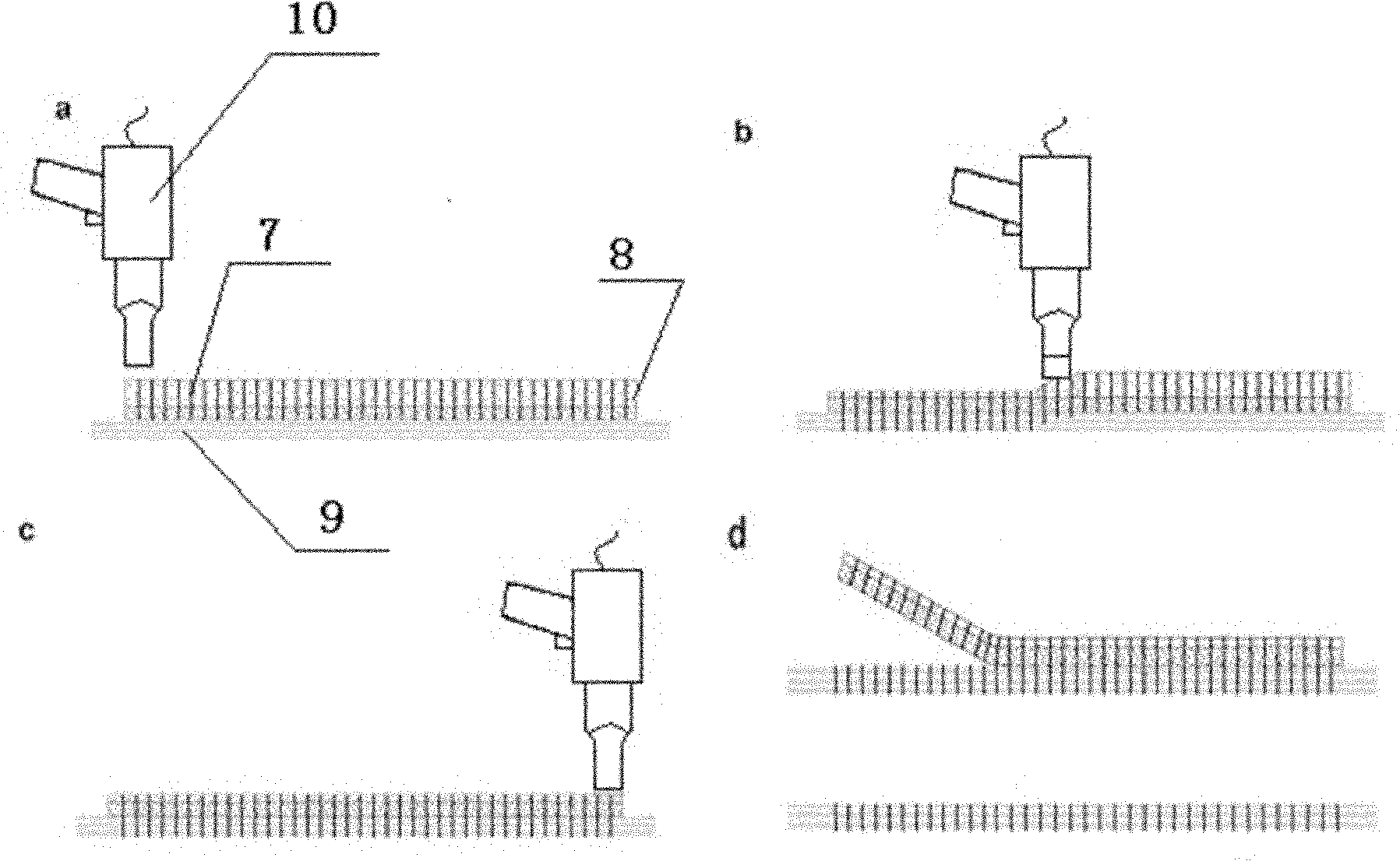
[0025] figure 2 For the process flow diagram of ultrasound-assisted implantation, refer to figure 2 As shown, the above-mentioned micro-diameter carbon fiber rod is cut into a fixed-length rod with a length of 6mm, and is evenly implanted into the foam carrier according to the volume fraction of 3.14%; the foam carrier implanted with the micro-diameter carbon fiber rod is placed on the composite material prepreg blank surface( figure 2 As shown in a), micro-diameter carbon fiber rods are vertically implanted into the laminated structure by ultrasonic-assisted equipment as [0] 24 5224 high-temperature epoxy resin-based domestic carbon fiber U3...
Embodiment 2
[0028] Carbon fiber (Toray T300-1K, Japan) was impregnated with bismaleimide resin (QC-130), and a micro-diameter carbon fiber rod with a diameter of 0.3 mm was prepared by pultrusion. The temperature of the glue tank was 95 ° C, and the mold temperature was 180 ° C. The pultrusion speed is 0.18m / min; the above-mentioned micro-diameter carbon fiber rod is cut into a fixed-length rod with a length of 5mm by a self-made numerical control implanter, and is evenly implanted into the foam carrier at a volume fraction of 0.44%; the micro-diameter carbon fiber rod is implanted The foam carrier is placed on the upper surface of the composite prepreg blank, and the micro-diameter carbon fiber rods are vertically implanted into the laminate structure by ultrasonic equipment as[0] 24 The 5224 high-temperature epoxy resin-based domestic carbon fiber U3160 prepreg, remove the foam, and obtain the resin-based composite material blank reinforced by the micro-diameter carbon fiber rod.
[002...
Embodiment 3
[0031] Carbon fiber (Toray T300-3K, Japan) is impregnated with epoxy resin (Kunshan Yubo Resin Factory FW-125 type), and a micro-diameter carbon fiber rod with a diameter of 0.5 mm is prepared by pultrusion. The temperature of the glue tank is 36 °C and the mold temperature is 129 °C. ℃, the pultrusion speed is 0.18m / min.
[0032] Cut the above-mentioned micro-diameter carbon fiber rod into a fixed-length rod with a length of 3 mm using a self-made numerical control implanter, and implant it into the foam carrier evenly at a volume fraction of 1.23%; place the foam carrier implanted with the micro-diameter carbon fiber rod on the composite material prepreg On the upper surface of the blank, the fixed-length micro-diameter carbon fiber rods are vertically implanted into the laminated structure by ultrasonic equipment as [0 2 / 90 / 0 2 / 90 / 0 2 / 90 / 0 3 ] S The HT7 / 5429 bismaleimide unidirectional carbon fiber prepreg is removed from the foam to obtain a resin-based composite bl...
PUM
| Property | Measurement | Unit |
|---|---|---|
| diameter | aaaaa | aaaaa |
Abstract
Description
Claims
Application Information
 - R&D
- Intellectual Property
- Life Sciences
- Materials
- Tech Scout
- Unparalleled Data Quality
- Higher Quality Content
- 60% Fewer Hallucinations
Browse by: Latest US Patents, China's latest patents, Technical Efficacy Thesaurus, Application Domain, Technology Topic, Popular Technical Reports.
© 2025 PatSnap. All rights reserved.Legal|Privacy policy|Modern Slavery Act Transparency Statement|Sitemap|About US| Contact US: help@patsnap.com


