
Active phased array antenna adopting passive loading way to control sidelobe level

A phased array antenna and mode control technology, which is applied to antennas, antenna arrays, circuits, etc., can solve the problems of high cost, and achieve the effect of reducing feed cost, reducing cost, and reducing side lobes

Active Publication Date: 2011-06-29
SHANGHAI INST OF MICROSYSTEM & INFORMATION TECH CHINESE ACAD OF SCI
View PDF5 Cites 59 Cited by
  • Summary
  • Abstract
  • Description
  • Claims
  • Application Information

AI Technical Summary

Problems solved by technology

For large active phased array antennas, the cost of the array is very expensive and is the main part of the radar cost

Method used


Image

  • Active phased array antenna adopting passive loading way to control sidelobe level
  • Active phased array antenna adopting passive loading way to control sidelobe level
  • Active phased array antenna adopting passive loading way to control sidelobe level

Examples


Embodiment Construction

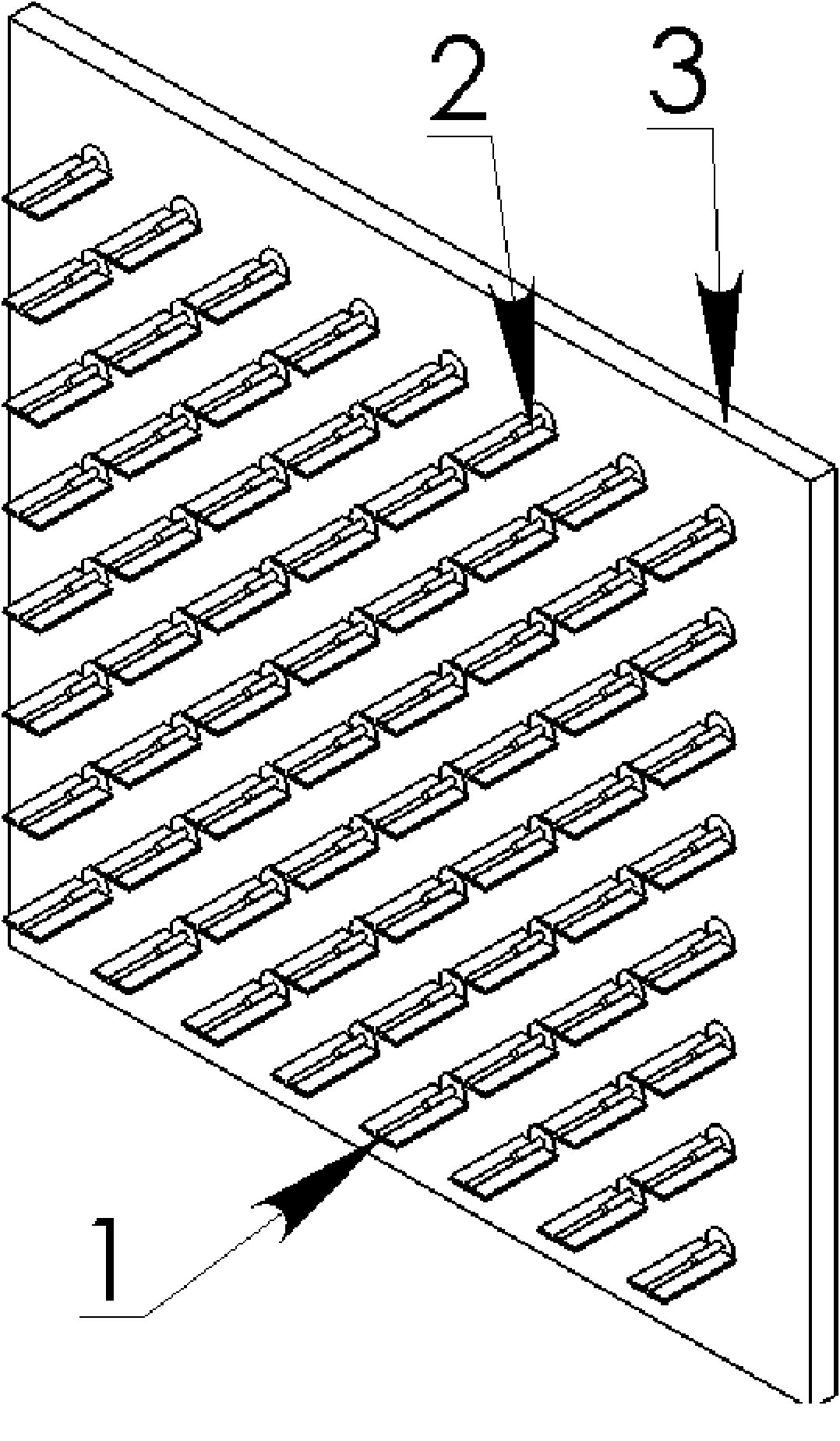
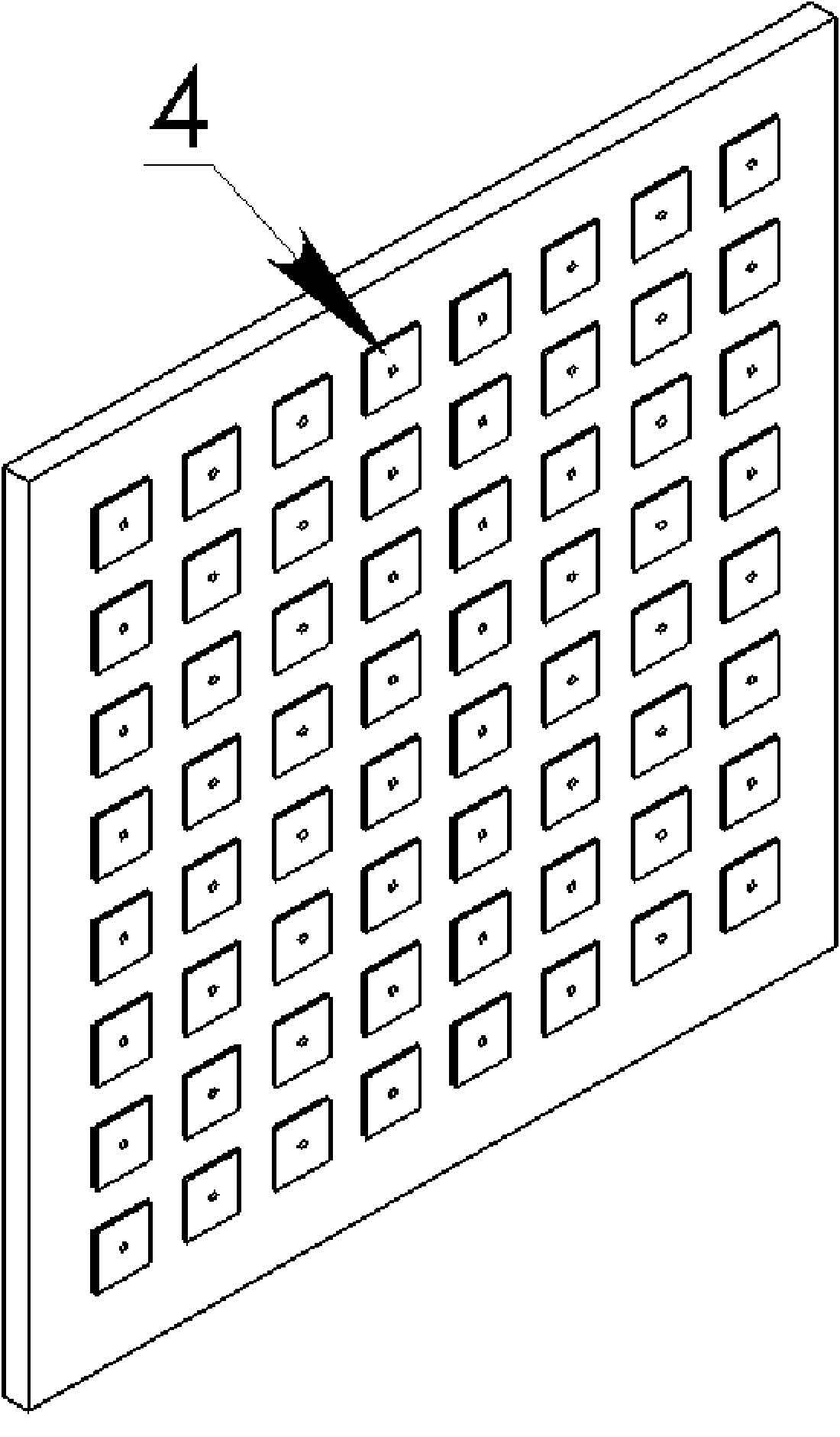
[0028] The substantive features and remarkable progress of the present invention will be further elaborated below in conjunction with the description of the accompanying drawings, but the present invention is by no means limited to the embodiments.

[0029] Such as figure 1 As shown, the entire active phased array antenna is composed of 64 antenna units, and the antenna units are arranged in a two-dimensional matrix of 8*8. In order to meet the maximum requirement of antenna beam scanning angle without grating lobes, the spacing of each radiating element is 0.5 free space wavelength. The feeding network is composed of 8 1*8 power dividers. The 8-way power divider is used to make each radiating unit have the same initial amplitude and phase.

[0030] figure 2 Shown is an active phased array antenna with 64 radiating elements excited simultaneously. The disadvantage of this antenna is that it has high sidelobes. Figure 5 and Figure 6 Respectively represent the square ape...


PUM


Abstract

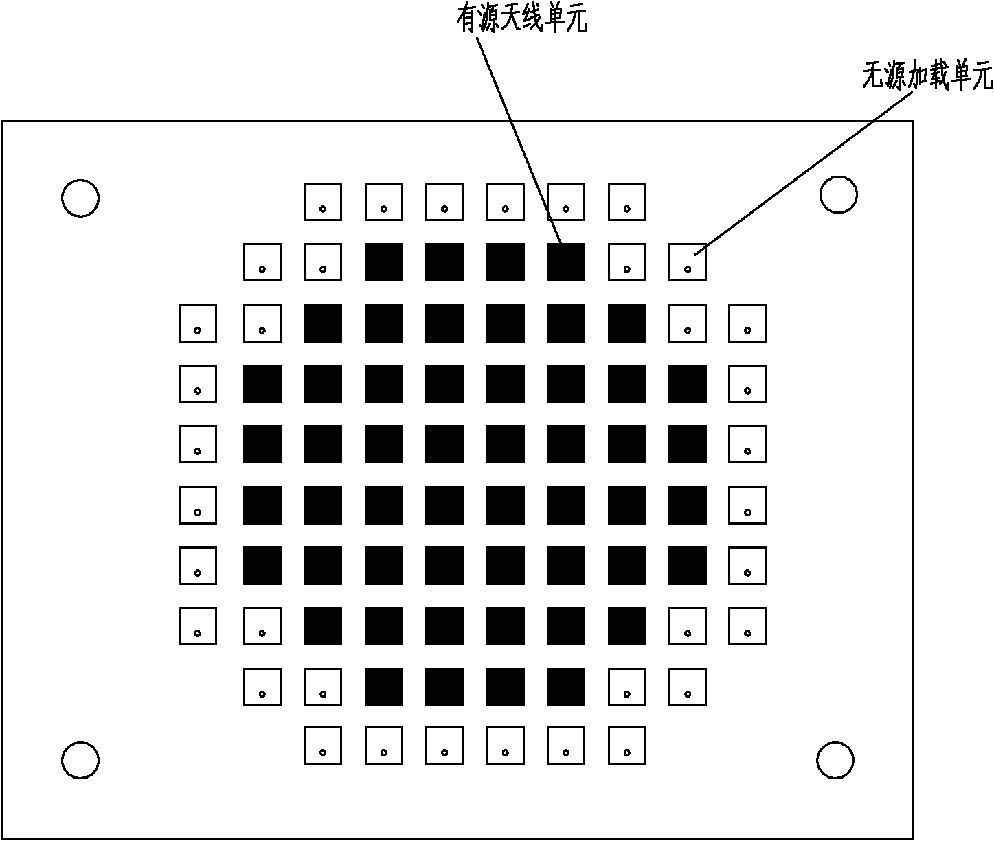
The invention relates to an active phased array antenna adopting the passive loading way to control sidelobe level, which is characterized in that the array surface of the active phased array antenna is jointly constituted by active loading units and passive loading units, and the passive loading units are positioned on the periphery of the active loading units; each active loading unit channel is controlled by an independent vector modulator and a low-noise amplifier, and each vector modulator simultaneously controls the amplitude and the phase of a feed source, thereby further changing the amplitude and the phase of surface current of the antenna units, and finally controlling the scanning angel of a wave beam and inhibiting the sidelobe level of the wave beam, wherein the active phasedarray transmitting antenna comprises 64 radiating units, the excitation way through a coaxial connector is adopted, the scanning of the spatial wave beam is realized by changing the phase distribution of the antenna on the pore diameter, and the required wave beam shape is obtained by changing the amplitude of the surface current on each radiation unit. The mutual coupling among array elements isutilized, thereby reducing the sidelobe level of the antenna in the pitching direction by 5dB in comparison with square fully array caliber feed on the basis of reducing the cost of the feed source.

Description

technical field [0001] The present invention relates to an active phased array antenna, more specifically the present invention relates to a method of passive loading and controlling the amplitude and relative phase of signals in multiple active transmitting units to obtain different beam shapes and Beams with different pitch angles. Background technique [0002] With the maturity of microwave / millimeter wave solid-state circuits, computers and digital signal processing levels, the "bottleneck" factors restricting the development of phased array antennas are gradually being overcome. Phased array antennas can enable satellite or ground communication systems to quickly change the antenna beam pointing and beam coverage shape, and it is a key technology that has developed rapidly in communication satellite payloads in recent years. Whether it is a large communication satellite in geostationary orbit or a small satellite in a medium or low orbit, the phased array unit of the d...

Claims


Application Information

Patent Timeline
IPC IPC(8): H01Q3/28H01Q3/34H01Q21/00
Inventor 孙芸孙晓玮韩克武杨明辉
Owner SHANGHAI INST OF MICROSYSTEM & INFORMATION TECH CHINESE ACAD OF SCI
Learn More