Interconnect for a fuel cell, a method for manufacturing an interconnect for a fuel cell

A technology of fuel cells and interconnects, applied in the field of interconnects

Active Publication Date: 2011-06-29
HALDOR TOPSOE AS
View PDF9 Cites 4 Cited by
  • Summary
  • Abstract
  • Description
  • Claims
  • Application Information

AI Technical Summary

Problems solved by technology

Although called a one-piece separator plate, the interconnection of US 5424144 still requires multiple metal insert rings to transfer the compressive force to the sealing body

Method used


Image

  • Interconnect for a fuel cell, a method for manufacturing an interconnect for a fuel cell
  • Interconnect for a fuel cell, a method for manufacturing an interconnect for a fuel cell
  • Interconnect for a fuel cell, a method for manufacturing an interconnect for a fuel cell

Examples


Embodiment Construction

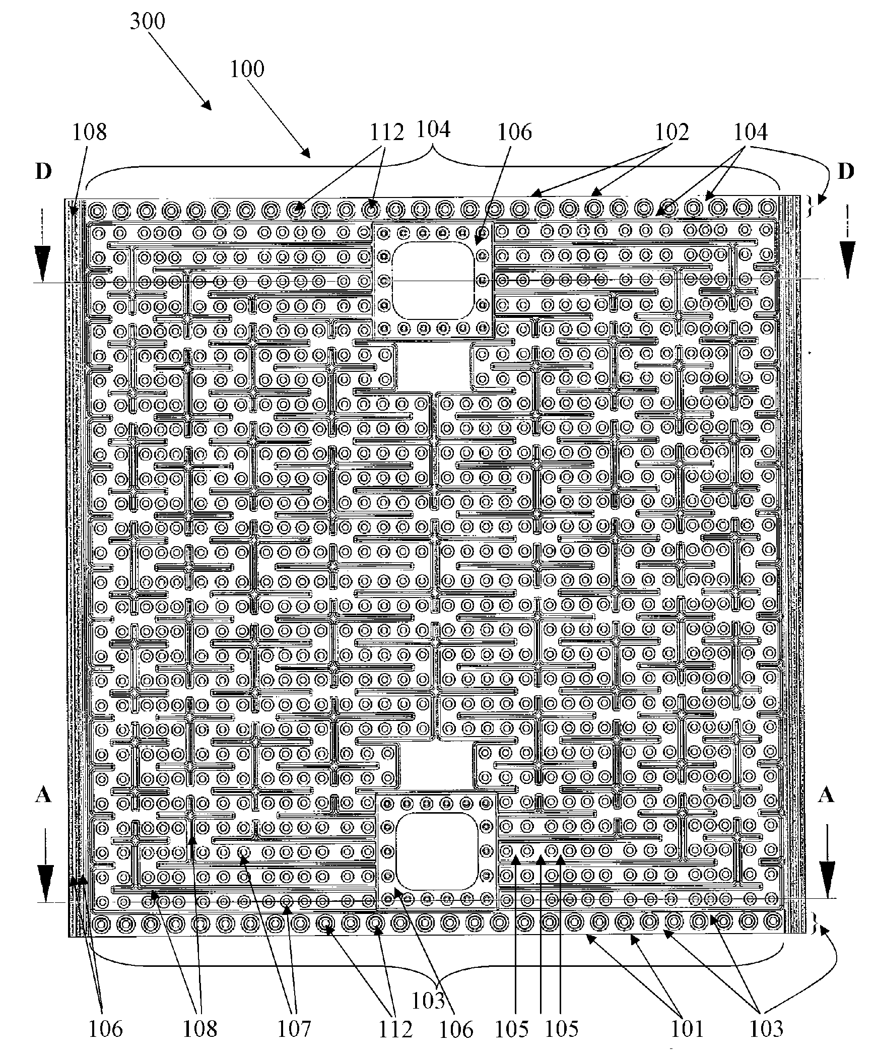
[0140] Figure 1-O A first side 100 of an interconnect 300 in the form of a rectangular plate defining four interconnect peripheral edges is shown. The interconnect shown here has a first side 100 on one face of the interconnect and a second side 200 on the opposite side shown in FIG. 2 , in this example the first side 100 is the interconnect The oxidant side of the member, the second side 200 is the fuel side of the interconnect. Oxidant gas, such as air, from an inlet oxidant manifold (not shown) is introduced into a first side oxidant inflow port 101 that extends along a relatively large portion of one peripheral edge of the interconnect. This type of inlet is characterized by an external manifold arrangement that directs flow to the inlet via an external manifold (not shown) that is sealed to the outer surface of the assembled fuel cell stack comprising A plurality of fuel cells according to the interconnection of the present invention.

[0141] Through the first side in...


PUM

PropertyMeasurementUnit
thicknessaaaaaaaaaa
thicknessaaaaaaaaaa
thicknessaaaaaaaaaa

Abstract

An interconnect for a fuel cell is made of pressed metal sheet. The interconnect integrates inlets and outlets, flow distributing inlet and outlet-zones seal surfaces and flow paths on both sides of the interconnect all formed and defined by discrete point or oblong protrusions made by the deformation of the sheet. A protrusion on one side of the interconnect corresponds to an indentation on the other side, but since the interconnect consists of three levels, the first side of the interconnect can be designed substantially independently of the second side.

Description

technical field [0001] The present invention relates to an interconnect for fuel cells produced by plastic deformation of thin metal sheets, whereby protrusions and recesses for flow paths, inlet and outlet regions, sealing surfaces and purge channels are integrated in in a single piece. Background technique [0002] The present invention will be explained in the context of a solid oxide fuel cell. However, the interconnect according to the invention can also be used in other types of fuel cells, such as polymer electrolyte fuel cells (PEM) or direct methanol fuel cells (DMFC). A solid oxide fuel cell (SOFC) includes a solid electrolyte, a cathode, and an anode. The solid electrolyte can conduct oxygen ions, where oxygen is reduced to oxygen ions at the cathode, and hydrogen is oxidized at the anode. The overall reaction in SOFC is that hydrogen and oxygen react electrochemically to generate electricity, heat and water. To generate the required hydrogen, the anode typical...

Claims


Application Information

Patent Timeline
Patent Type & Authority Applications(China)
IPC IPC(8): H01M8/02
CPCH01M8/0258H01M8/04089H01M2008/147H01M8/1011Y02E60/50H01M8/0662H01M2008/1095Y02E60/523H01M8/0208Y02E60/525H01M8/021H01M2008/1293Y02E60/526H01M8/0254Y02P70/50H01M8/2483H01M8/2425H01M8/02B23P17/00H01M8/10H01M8/14H01M8/0276H01M8/241
Inventor N·埃里克斯特鲁普
Owner HALDOR TOPSOE AS
Why Eureka
Try Eureka