Multi-side milling machine and hydraulic clamp for same

A technology for hydraulic fixtures and milling machines, applied in the field of machine tools, can solve problems such as hidden safety hazards, connection failures, and high labor intensity, and achieve the effects of improving the production environment, improving work efficiency, and improving processing quality.

Inactive Publication Date: 2011-07-06
上海嘉仕久企业发展有限公司
View PDF3 Cites 14 Cited by
  • Summary
  • Abstract
  • Description
  • Claims
  • Application Information

AI Technical Summary

Problems solved by technology

Five times of positioning and clamping is not only inefficient, but more importantly, this processing method is difficult to ensure the processing accuracy, and at the same time, the manual operation of the workers is labor-intensive.
The traditional fixture uses bolts and pressure plates to press the workpiece. Since the bolts and nuts are prone to wear and tear during frequent loading and unloading, the connection will fail, posing safety hazards and labor-intensive.
In short, the use of traditional equipment has a high rate of defective products, low efficiency, and high labor intensity.

Method used


Image

  • Multi-side milling machine and hydraulic clamp for same
  • Multi-side milling machine and hydraulic clamp for same
  • Multi-side milling machine and hydraulic clamp for same

Examples


Embodiment Construction

[0022] The present invention will be further described below in conjunction with accompanying drawing.

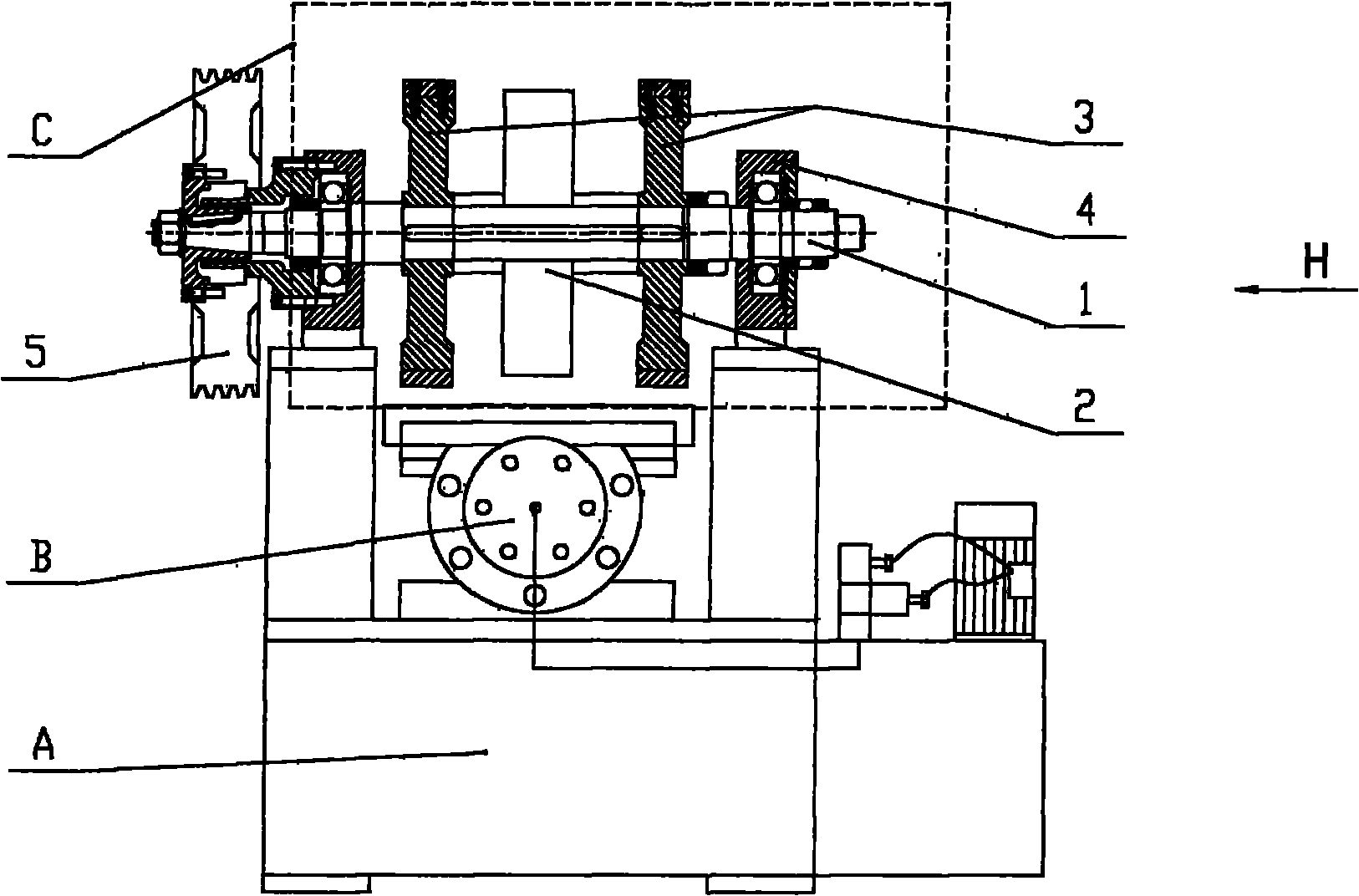
[0023] figure 1 The middle bed A is fixed with a sliding seat and a power head C that cooperate with the hydraulic sliding table B, and the hydraulic sliding table B can move along the vertical direction of the main shaft of the power head C on the sliding seat.

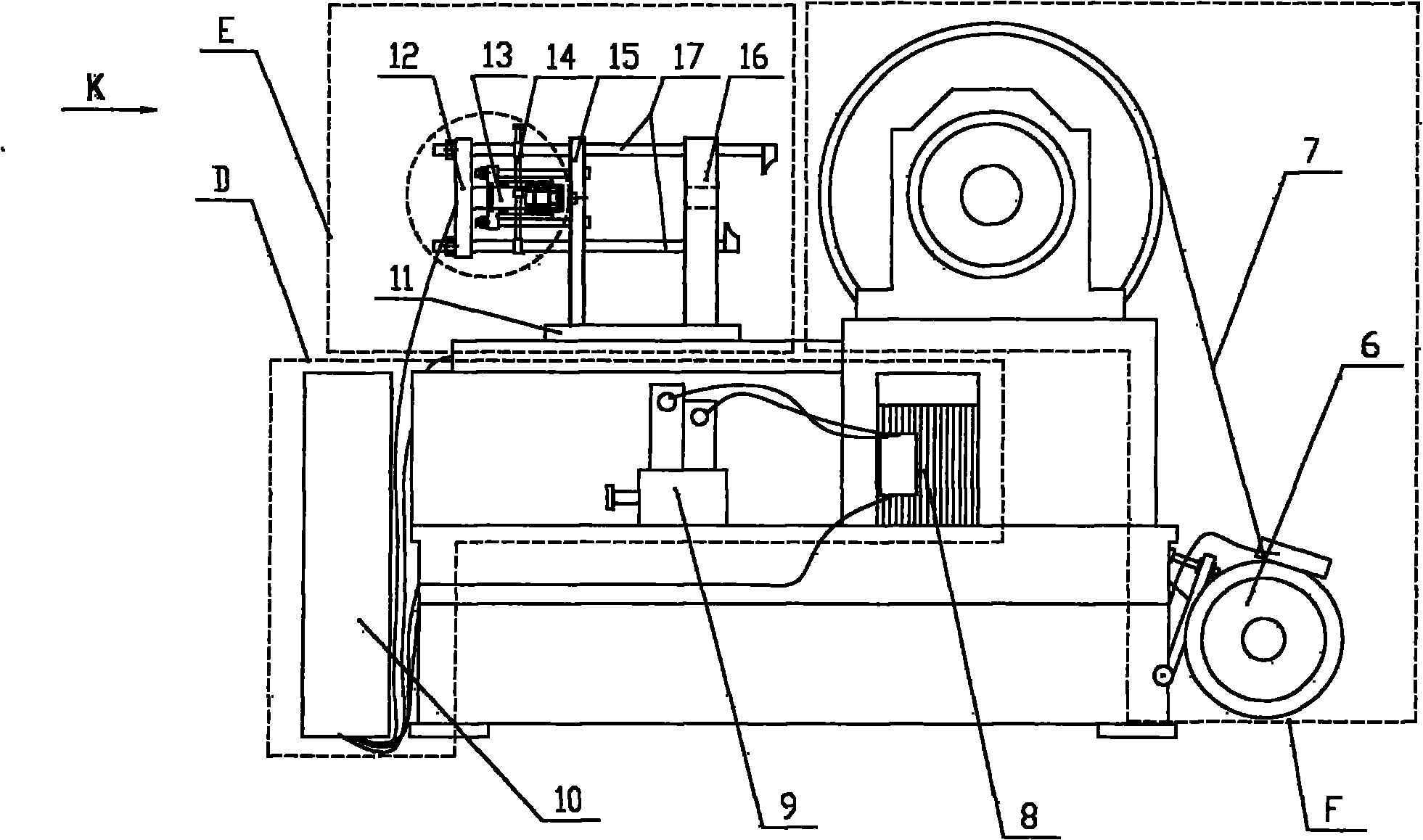
[0024] The driving device F in the dotted line frame is composed of a pulley 5, a motor 6 and a belt 7. Its working principle is: the hydraulic station D controls the operation of the motor 6, and drives the pulley 5 to rotate through the transmission of the belt 7, thereby driving the main shaft of the power head to rotate.

[0025] The power head C in the dotted line box is composed of a main shaft 1, a three-sided milling cutter disc 2, two milling cutter discs 3 and a bearing seat 4. The three-sided milling cutter disc 2 is located in the middle of the main shaft, and two milling cutter discs 3 are located at ...


PUM


Abstract

The invention provides a multi-side milling machine and a hydraulic clamp for the same. The multi-side milling machine comprises a hydraulic sliding table (B), a hydraulic station (D), the hydraulic clamp (E) and a power head (C), wherein the hydraulic sliding table (B) is used for making the hydraulic clamp on the sliding table move forward and backward; the hydraulic station (D) controls the running of a motor, the movement of the sliding table and the clamping of the clamp; the hydraulic clamp (E) is used for clamping a work piece; and the power head (C) is arranged on a machine body. Power is supplied by the motor 6, and a belt wheel drives a main shaft of the power head (C) to rotate, so that the rotation of milling cutter disks arranged on the shaft is realized. The left and right milling cutter disks mill an external surface of a steering knuckle, and the middle three-blade milling cutter disk mills an internal surface and a bottom plane of the steering knuckle simultaneously. By the invention, the simultaneous processing of the four side faces and the bottom plane of parts of the steering knuckle is realized, and the work piece is clamped automatically; moreover, the production efficiency is high, the processing quality is high, the labour strength is low and production environment is also improved.

Description

technical field [0001] The invention relates to a machine tool, in particular to a milling machine, in particular to a machine tool for simultaneously milling multiple surfaces of steering knuckle parts. It also relates to a hydraulic clamp, in particular to a hydraulic clamp suitable for clamping workpieces with hydraulic oil cylinders during steering knuckle machining. Background technique [0002] Among the mechanical parts, there is a kind of steering knuckle parts that need to be milled on the four sides of the fork and the bottom plane of the disc. In order to complete the processing of such parts as steering knuckle products, domestic manufacturers generally adopt five times of clamping and five times of processing, and only process one surface each time. Performing five times of positioning and clamping is not only inefficient, but more importantly, this processing method is difficult to ensure the processing accuracy, and at the same time, the manual operation of w...

Claims


Application Information

Patent Timeline
Patent Type & Authority Applications(China)
IPC IPC(8): B23C3/00B23Q1/25B23Q5/10B23Q3/06
Inventor 祁斌陆善明
Owner 上海嘉仕久企业发展有限公司
Why Eureka
Try Eureka