Flexible dual-drive biomimetic fish with variable drive position

A bionic fish and dual-drive technology, applied in the direction of non-rotating propulsion elements, can solve the problems of poor maneuverability and poor stability, and achieve the effects of simple structure, improved stability, and improved control accuracy

Inactive Publication Date: 2011-07-06
HARBIN INST OF TECH
View PDF3 Cites 14 Cited by
  • Summary
  • Abstract
  • Description
  • Claims
  • Application Information

AI Technical Summary

Problems solved by technology

[0003] The purpose of the present invention is to solve the problems of poor stability and poor maneuverability of the existing bionic robotic fish, and provide a flexible dual-drive bionic fish with variable driving positions

Method used


Image

  • Flexible dual-drive biomimetic fish with variable drive position
  • Flexible dual-drive biomimetic fish with variable drive position
  • Flexible dual-drive biomimetic fish with variable drive position

Examples


specific Embodiment approach 1

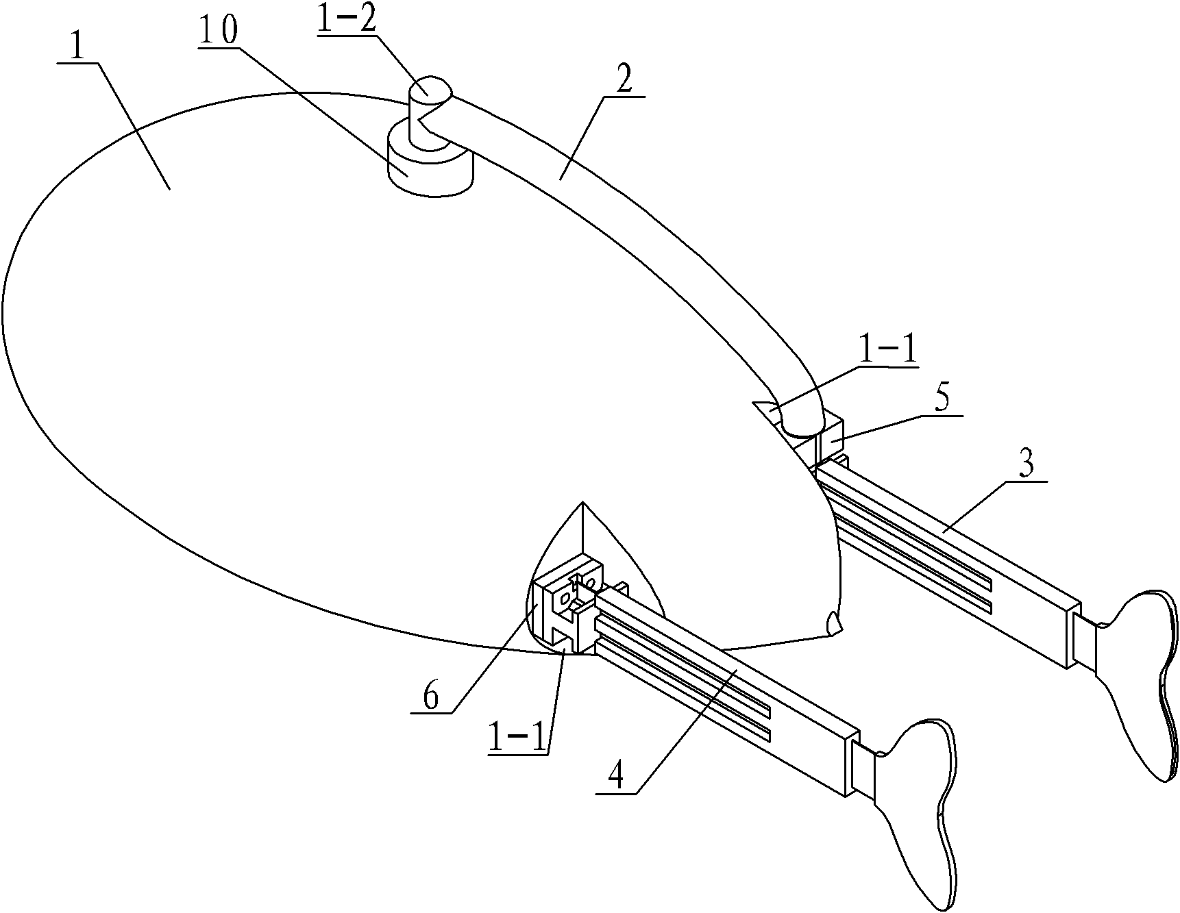
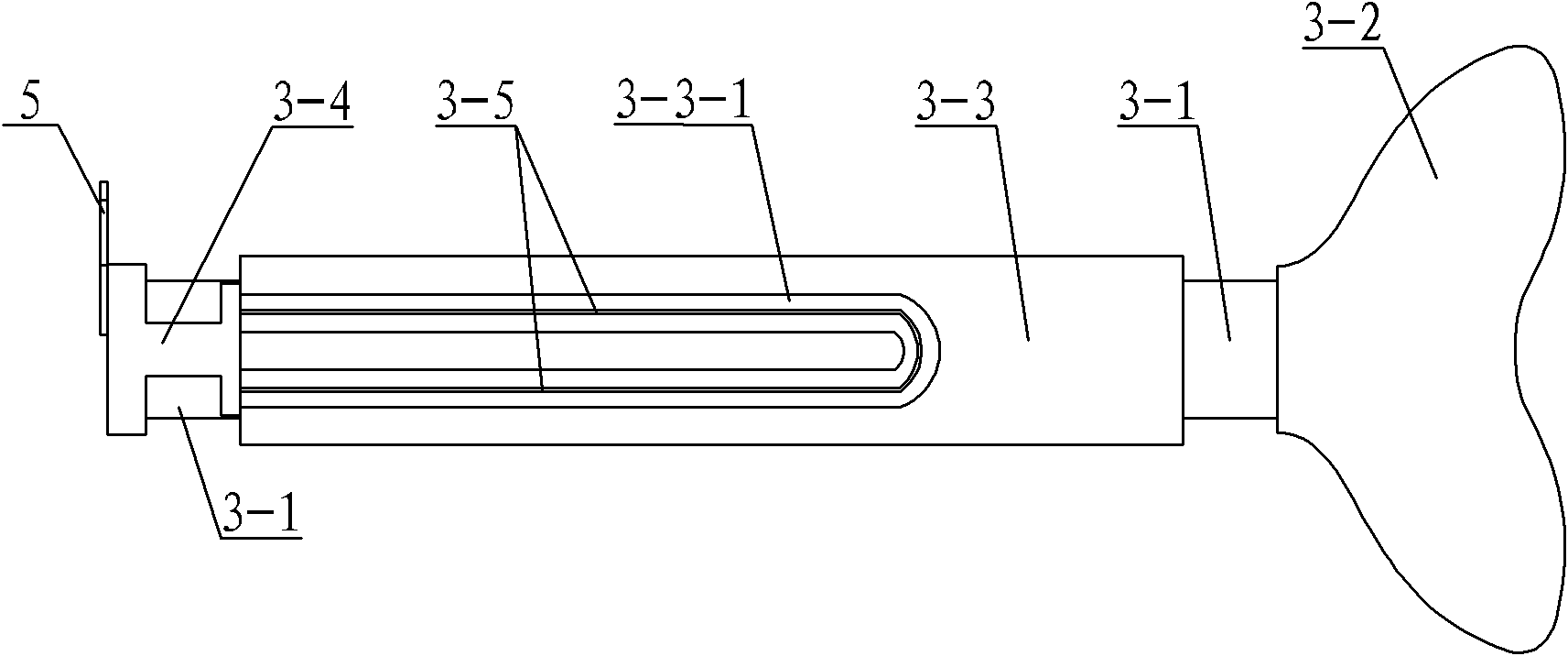
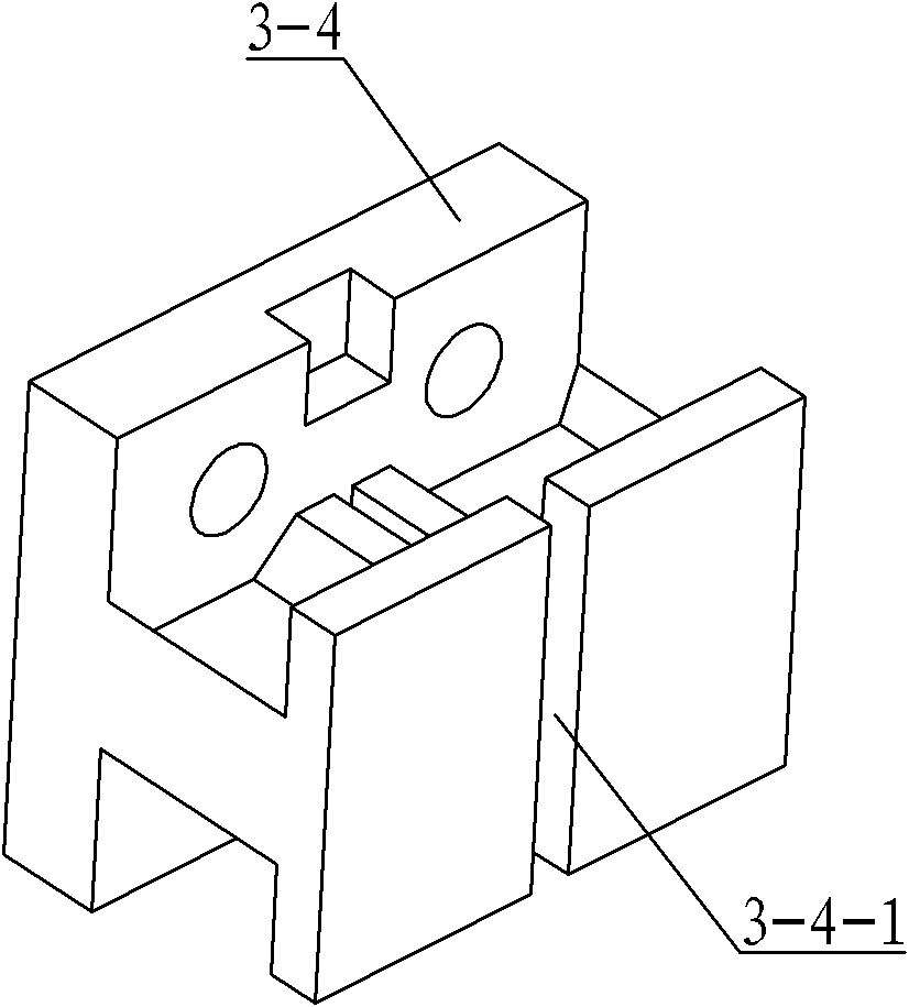
[0007] Specific implementation mode one: combine Figure 1 ~ Figure 3 Describe this embodiment, this embodiment includes bionic fish body 1, rotating beam 2, movable caudal fin driver 3, fixed caudal fin driver 4, connecting piece 5 and spacer 6, movable caudal fin driver 3 and fixed caudal fin driver 4 are all made of elastic substrate 3-1, fish tail 3-2, silica gel layer 3-3, shape memory alloy wire fixing seat 3-4 and two shape memory alloy wires coated with insulating layer 3-5, shape memory alloy wire fixing seat 3- 4. There is a gap 3-4-1 on the outer end surface, and one end of the elastic substrate 3-1 is inserted into the gap 3-4-1 on the shape memory alloy wire holder 3-4, and the other end of the elastic substrate 3-1 One end is connected to the fishtail 3-2, the silicone layer 3-3 is wrapped on the outer surface of the elastic substrate 3-1, and the silicone layer 3-3 on the two outer surfaces of the elastic substrate 3-1 is symmetrically provided with alloy wire g...

specific Embodiment approach 2

[0009] Specific implementation mode two: combination figure 1 To describe this embodiment, the rotating beam 2 in this embodiment is an arched beam. This design can reduce the resistance of the rotating beam 2, thereby reducing the resistance of the bionic fish body 1. Other components and connections are the same as those in the first embodiment.

specific Embodiment approach 3

[0010] Specific implementation mode three: combination figure 1 Describe this embodiment, the distance between the movable tail fin driver 3 and the fixed tail fin driver 4 of this embodiment is greater than 2.5 times of the maximum amplitude of the movable tail fin driver 3 or the fixed tail fin driver 4 . This design can avoid mutual interference of eddy currents generated when the two fishtails 3-2 swing. Other components and connections are the same as those in the first embodiment.

[0011] Working principle of the present invention: first the ends of two shape memory alloy wires 3-5 coated with an insulating layer on the fixed tail fin driver 4 are all passed through the shape memory alloy wire holder 3-4 on the fixed tail fin driver 4, The gasket 6, the end face of the driver installation groove 1-1 are respectively connected with the drive circuit 8 in the bionic fish body 1; the ends of the two shape memory alloy wires 3-5 coated with an insulating layer on the movab...


PUM


Abstract

The invention discloses a flexible dual-drive biomimetic fish with a variable drive position, relating to a biomimetic robot fish which is used for solving the defects of poor stability and bad maneuverability of the traditional biomimetic fish. A movable tail fin driver and a fixed tail fin driver of the biomimetic fish respectively comprises an elastic basic sheet, a fish tail, a silicon gel layer, a shape memory alloy wire fixed seat and two shape memory alloy wires coated with insulating layers, wherein the movable tail fin driver and the fixed tail fin driver are parallel with a longitudinal centre line of a biomimetic fish body and symmetrically arranged relative to the longitudinal centre line of the biomimetic fish body; the two shape memory alloy wire fixed seats are respectivelyarranged in corresponding driver installing grooves, the shape memory alloy wire fixed seat on the fixed tail fin driver is fixedly connected with the biomimetic fish body through a shim, the shape memory alloy wire fixed seat on the movable tail fin driver is fixedly connected with one end of a rotating cross beam through a connecting sheet, and the other end of the rotating cross beam is fixedly connected with a steering engine shaft on the biomimetic fish body. The invention is used for underwater detection.

Description

technical field [0001] The invention relates to a double-drive bionic fish. Background technique [0002] At present, in the application of underwater detection and reconnaissance, there is an urgent need for a tiny underwater robot that can be stable, flexible, and highly maneuverable in water or other liquids. It can be driven wirelessly in a liquid environment and has high mobility and flexibility. The bionic robot fish is one of the tiny devices with this function. The patent application number is 200610151170.5, the publication number is CN 1986330A, and the invention patent application with the publication date on June 27, 2007 discloses a double-tail bionic tail propeller; The wheel and crank linkage mechanism drives the rigid tail handle to swing, which mainly solves the problem of the bow of the ship; however, because the patent application is rigidly driven by the motor, there are problems of low driving efficiency, high noise and poor maneuverability. The patent...

Claims


Application Information

Patent Timeline
Patent Type & Authority Applications(China)
IPC IPC(8): B63H1/36
Inventor 杨征保王玉魁王振龙宋超男马聪郭程
Owner HARBIN INST OF TECH
Why Eureka
Try Eureka