Distributed power multi-rotor VTOL (vertical take off and landing) aircraft and control method thereof

A vertical take-off and landing, flight control technology, applied in the aerospace field, can solve problems such as loss of lift, loss of control of aircraft flight attitude, loss of human, material and financial resources, etc., to achieve the effect of improving reliability and reducing the risk of crashes

Inactive Publication Date: 2011-07-06
文杰
View PDF13 Cites 64 Cited by
  • Summary
  • Abstract
  • Description
  • Claims
  • Application Information

AI Technical Summary

Problems solved by technology

[0008] However, there is a common defect in the existing vertical take-off and landing aircraft: due to the limitation of its flight principle, the reliability of this type of aircraft is relatively poor-when there are mechanical failures such as engine shutdown or rotor breakage, the aircraft will fail due to flight

Method used


Image

  • Distributed power multi-rotor VTOL (vertical take off and landing) aircraft and control method thereof
  • Distributed power multi-rotor VTOL (vertical take off and landing) aircraft and control method thereof
  • Distributed power multi-rotor VTOL (vertical take off and landing) aircraft and control method thereof

Examples


Embodiment 1

[0066] Embodiment 1: Distributed power multi-rotor vertical take-off and landing aircraft with four lift power units

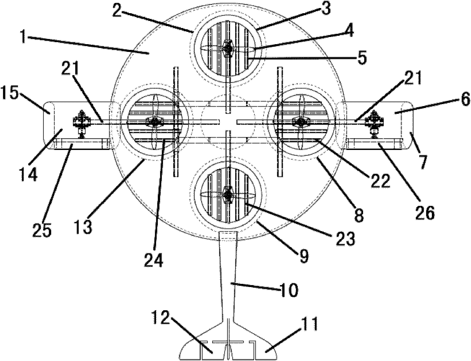
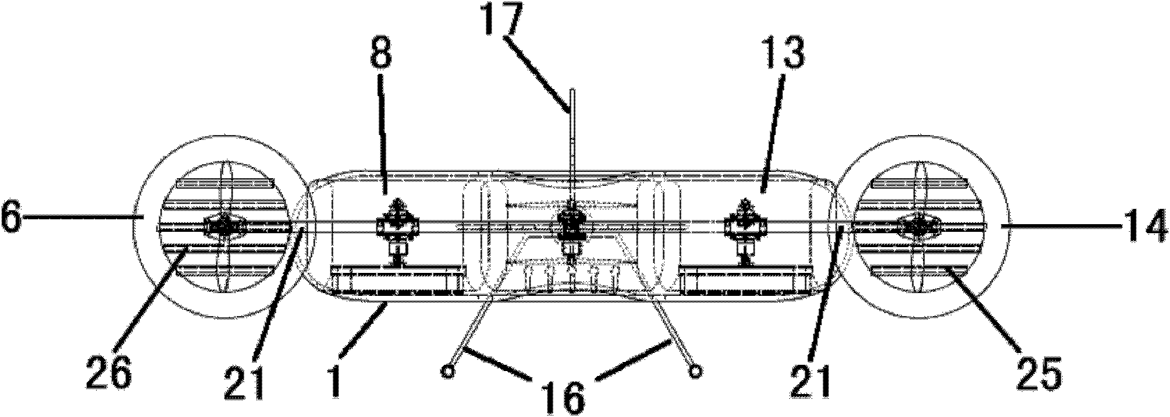
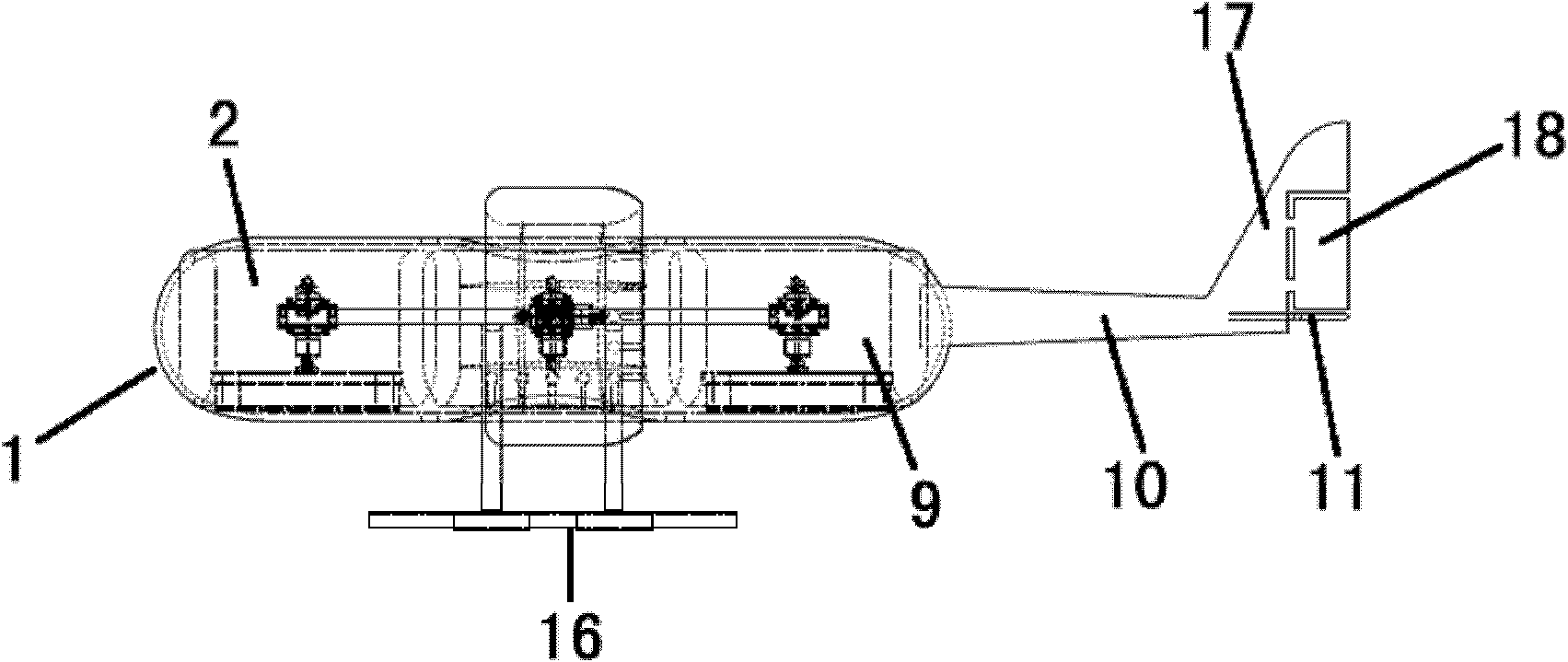
[0067] Such as Figure 1-4 As shown, it is the structural representation of the distributed power multi-rotor vertical take-off and landing aircraft and the structural representation of the power unit of Embodiment 1 of the present invention; On the airframe, several lift power units and thrust power units installed in the fairing 1, as well as the central flight control computer system.

[0068] Wherein the fairing 1 is used to reduce the air resistance when the aircraft is in level flight. At the same time, in the level flight state, the fairing can also provide lift.

[0069] In this embodiment, four lift power units are set as an example, which are respectively a front lift power unit 2, a rear lift power unit 9, a left lift power unit 13 and a right lift power unit 8. The four lift power units are evenly Set in the four directions of the front, rear, l...

Embodiment 2

[0145] Embodiment 2: Distributed power multi-rotor vertical take-off and landing aircraft with five lift power units

[0146] Such as Figure 5-7 As shown, it is a schematic structural diagram of the distributed power multi-rotor vertical take-off and landing aircraft of the second embodiment of the present invention; the difference between this embodiment and the previous embodiment is that the aircraft of this embodiment has five lift power units: front lift Power unit 2, left front lift power unit 30, right front lift power unit 27, left rear lift power unit 29 and right rear lift power unit 28, five lift power units in total, evenly arranged on the aircraft body, adjacent two lift power units The included angles between the lines connecting the geometric center of the power unit to the center of gravity of the aircraft are equal.

[0147] The structure of each lift power unit is the same as that of the front lift power unit 2, and is the same as that of the lift power uni...

Embodiment 3

[0199] Embodiment 3: Distributed power multi-rotor vertical take-off and landing aircraft with six lift power units

[0200] Such as Figure 8-Figure 11 As shown, it is a schematic structural diagram of a distributed multi-rotor vertical take-off and landing aircraft according to Embodiment 3 of the present invention: the difference between this embodiment and the preceding embodiments is that this embodiment includes six lift power units: front lift power unit 2, The left front lift power unit 30, the right front lift power unit 27, the left rear lift power unit 29, the right rear lift power unit 28, and the rear lift power unit 9 are evenly arranged on the aircraft body. The angles between the lines connecting the geometric centers of two adjacent lift power units to the center of gravity of the aircraft are equal. The structure of each lift power unit is the same as that of the front lift power unit 2 .

[0201] Wherein, the left side thrust power unit 14 and the right si...


PUM


Abstract

The invention relates to the field of aerospace engineering, specifically discloses a distributed power multi-rotor VTOL (vertical take off and landing) aircraft and a control method thereof. The aircraft comprises an aircraft body, a plurality of lift power units, a plurality of thrust power units, and a central flight control computer system, wherein the aircraft body is provided with a cowling covering outside the aircraft body; the lift power units and the thrust power units are uniformly arranged on the aircraft body and used for adjusting the attitude and speed of the aircraft; and the central flight control computer system is connected with the lift power units and the thrust power units and used for controlling the lift power units and the thrust power units to adjust the attitude and speed of the aircraft. Through uniformly setting a plurality of lift power units on the aircraft, the reliability, stability and disaster-tolerant capacity of the aircraft are improved, so that the aircraft still can fly normally when the components such as engines or rotors of the aircraft have mechanical failures, thereby reducing crash risk of the aircraft.

Description

technical field [0001] The invention relates to the field of aerospace technology, in particular to a distributed power multi-rotor vertical take-off and landing aircraft and a control method thereof. Background technique [0002] At present, the most common aircraft capable of vertical take-off and landing is a rotary-wing helicopter (referred to as "helicopter"). Helicopter is mainly composed of airframe and lift system (including main rotor and tail rotor), power system, transmission system and airborne flight equipment. The main rotor of a helicopter is generally driven by a turboshaft engine or a piston engine through a mechanical transmission system composed of a transmission shaft, a reducer, etc., and can also be driven by the reaction force generated by the tip jet. The helicopter engine drives the main rotor to provide lift and lift the helicopter in the air. The main engine also outputs power to the tail rotor at the tail of the aircraft. The onboard gyroscope c...

Claims


Application Information

Patent Timeline
IPC IPC(8): B64C27/08B64C27/12B64D27/24
Inventor 文杰
Owner 文杰
Why Eureka
Try Eureka