
Constant-temperature sonic nozzle process gas flow calibration facility and constant-temperature stagnation vessel

A stagnant container and sonic nozzle technology, applied in the field of gas flowmeter verification and calibration devices, can solve the problems of stagnant container vibration, vibration noise, and high overall power, so as to eliminate the influence of verification and calibration and reduce high-frequency vibration , the effect of reducing working noise

Inactive Publication Date: 2011-07-06
丹东科泰仪器仪表有限公司
View PDF4 Cites 3 Cited by
  • Summary
  • Abstract
  • Description
  • Claims
  • Application Information

AI Technical Summary

Problems solved by technology

Usually, the most obvious influence on the temperature in the verification environment is: when the flow rate is relatively large, a large amount of outdoor air of different temperatures enters the room, causing a large temperature change; when indoor air circulation is used, due to the large flow rate Among them, the overall power of the vacuum pump or air compressor is relatively large, and a vacuum pump or air compressor of several hundred kilowatts generates a lot of heat during operation, which will accumulate and increase with the prolongation of the verification working time, resulting in higher and higher temperature of the recycled air. , so as to seriously affect the test effect
In addition, during the operation of the current sonic nozzle gas flow standard device, when the verification flow rate is relatively large, the stagnant container and other components will generate vibration and vibration noise, which are also undesirable.
The above technical problems generally exist in various existing sonic nozzle gas flow standard devices, and there is no corresponding effective technical solution

Method used


Image

  • Constant-temperature sonic nozzle process gas flow calibration facility and constant-temperature stagnation vessel
  • Constant-temperature sonic nozzle process gas flow calibration facility and constant-temperature stagnation vessel
  • Constant-temperature sonic nozzle process gas flow calibration facility and constant-temperature stagnation vessel

Examples


Embodiment Construction

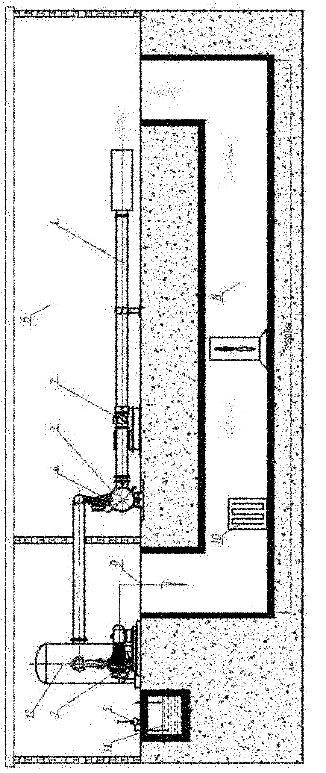
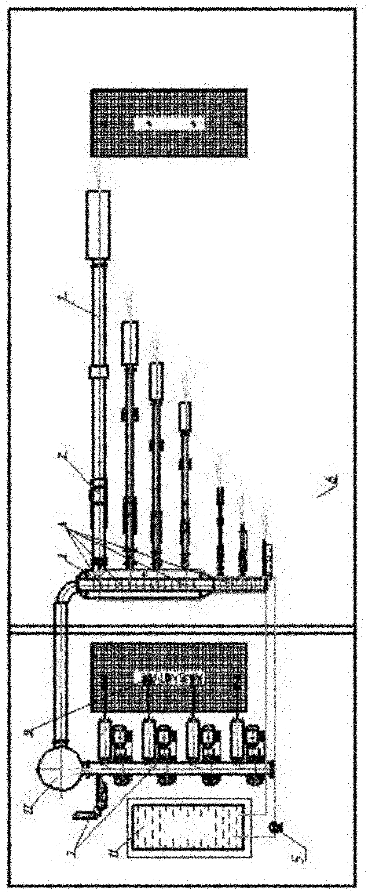
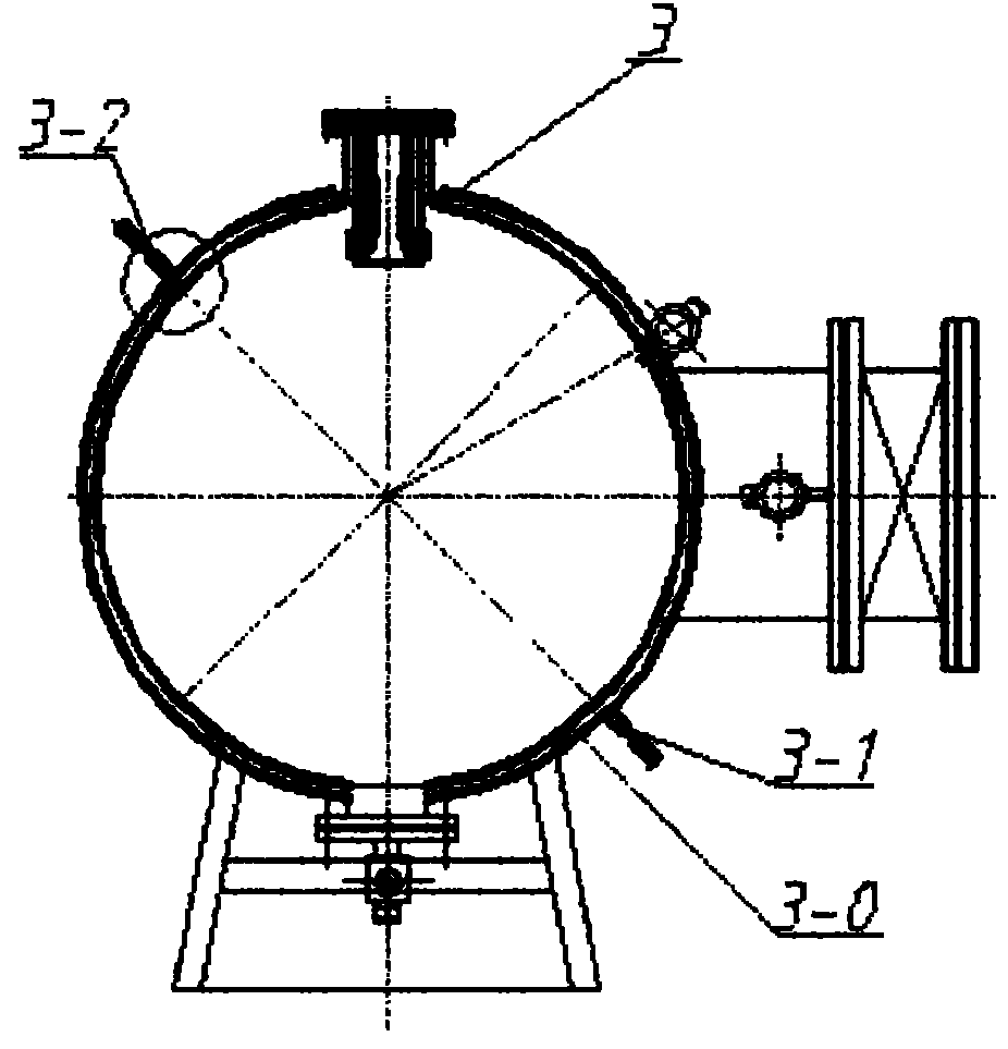
[0014] The constant temperature sonic nozzle method gas flow standard device claimed in the application of the present invention, such as figure 1 As shown, it includes a straight pipeline 1 before the meter connected in sequence, a flow meter 2 to be tested, a stagnation container 3 with a sonic nozzle 4 as a standard meter, and an air source assembly. The air source assembly includes a vacuum pump or an air The press 7, the pressure storage tank 12, the suction and exhaust pipeline and the muffler are composed, wherein the container wall of the stagnation container 3 adopts the water interlayer container wall 3-0, the water inlet pipe 3-1 of the water interlayer type container wall 3-0 and The water outlet pipe 3-2 is connected to the constant temperature water storage body. In the structure of this embodiment, the constant temperature water storage body is a constant temperature pool 11, and a circulating drive water pump 5 is set to form a water circulation channel together...


PUM


Abstract

The invention provides a constant-temperature sonic nozzle process gas flow calibration facility and a constant-temperature stagnation vessel. The constant-temperature sonic nozzle process gas flow calibration facility comprises a straight pipe line in front of a meter, a detected flowmeter, a stagnation vessel and a gas source assembly which are connected in sequence, wherein the stagnation vessel is provided with a sonic nozzle as a standard meter, a wall of the stagnation vessel is a vessel wall with a water interlayer, a water inlet pipe and a water outlet pipe of the vessel wall with the water interlayer are communicated with a constant-temperature water storage body, and a circulating driving pump is arranged to form a constant temperature circulating channel. In the technical scheme, the effect of external factors on detection temperature is prevented, so that the whole gas flow detection and calibration operation to be accurately carried out in a stable condition, the high-frequency vibration can be greatly reduced and the working noise can be greatly lowered.

Description

technical field [0001] The patent application of the present invention relates to a gas flow meter verification and calibration device. Background technique [0002] Such as figure 1 As shown, the basic components of the existing sonic nozzle method gas flow standard device include the experimental pipeline 1 before the meter, the flowmeter 2 to be tested, the sonic nozzle standard flowmeter 4 arranged in the stagnation container 3, and the vacuum pump (or air compressor) 7-based air source assembly. Its working principle is: the vacuum pump (or air compressor) works, and the suction air is discharged through the upstream experimental pipeline, the flow meter to be tested, the sonic nozzle and the vacuum pump (or air compressor). According to the principle of gas dynamics, When the pressure ratio between the upstream and downstream of the sonic nozzle reaches a critical state, and the airflow at the throat of the sonic nozzle reaches the speed of sound or local sonic speed...

Claims


Application Information

Patent Timeline
Patent Type & Authority Applications(China)
IPC IPC(8): G01F25/00
Inventor 李旭
Owner 丹东科泰仪器仪表有限公司
Learn More