Light guide plate manufacturing method, light guide plate, backlight module and liquid crystal display
A manufacturing method and backlight module technology, applied in chemical instruments and methods, instruments, optics, etc., can solve problems affecting light utilization rate, reflective sheet falling off, etc., save time, manpower and material resources, improve yield rate, and have strong adhesion Effect
- Summary
- Abstract
- Description
- Claims
- Application Information
AI Technical Summary
Problems solved by technology
Method used
Image

Examples
Embodiment 1
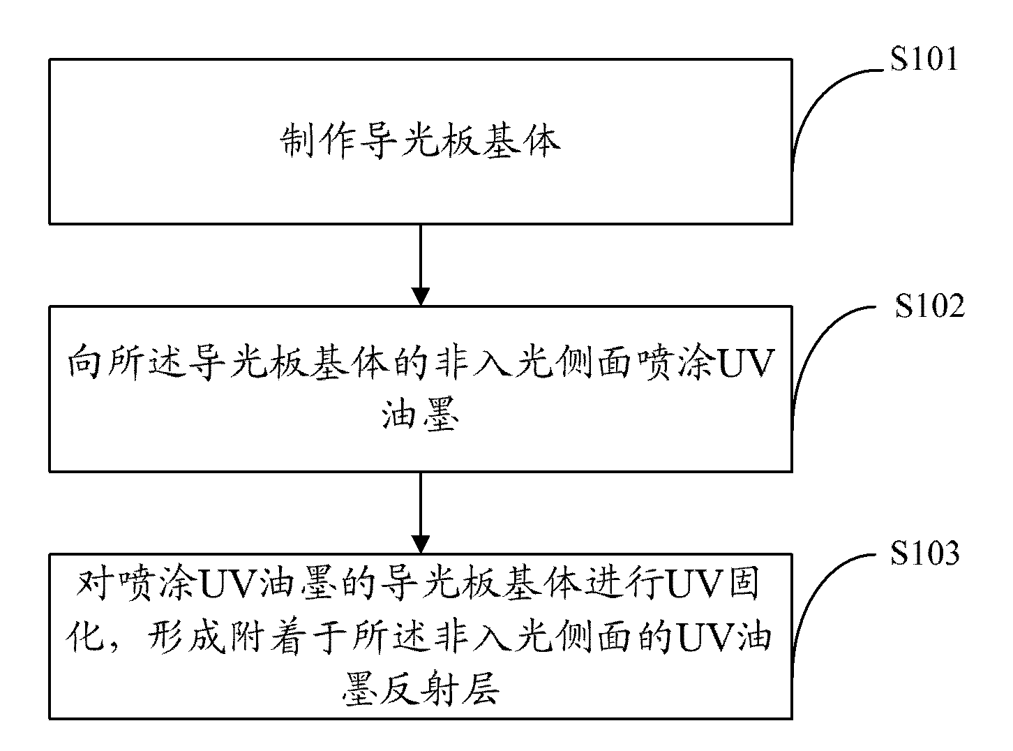
[0028] figure 1 The flow chart of the manufacturing method of the light guide plate provided by the first embodiment of the present invention is shown, and for the convenience of description, only the parts related to this embodiment are shown.
[0029] The manufacturing method of the light guide plate includes the following steps:
[0030] In step S101, a light guide plate base is fabricated.
[0031] In step S102, UV ink is sprayed on the non-light incident side of the light guide plate base.
[0032] This step is to spray the non-light source side of the light guide plate. The so-called "non-light-incident side" refers to the side where no light source is installed or no light is incident on the light guide plate when it is placed in the backlight module.
[0033] In step S103, UV curing is performed on the base of the light guide plate sprayed with UV ink to form a UV ink reflective layer attached to the non-light-incident side.
[0034] In this embodiment, the step of ...
Embodiment 2
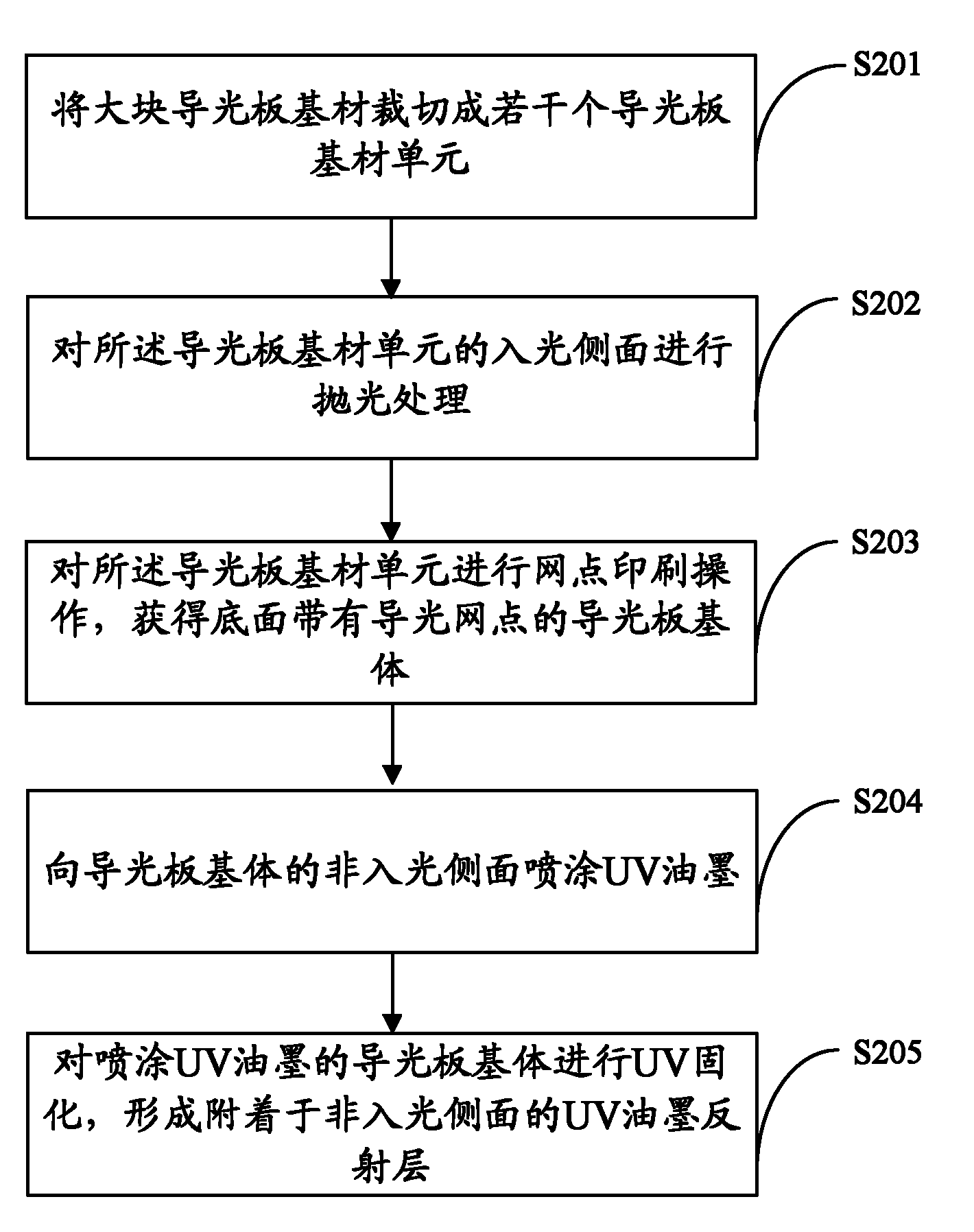
[0038] figure 2 The flow chart of the manufacturing method of the light guide plate provided by the second embodiment of the present invention is shown, and for the convenience of description, only the parts related to this embodiment are shown.
[0039] The base of the light guide plate in the first embodiment above may have the structure of a traditional light guide plate, with light guide dots printed on its bottom surface. At this time, the steps of making the base of the light guide plate may specifically include the following steps:
[0040] In step S201, the bulk light guide plate base material is cut into several light guide plate base material units of required size.
[0041] In step S202, the light-incident side surface of the light guide plate base unit is polished.
[0042] In this step, multiple light guide plate substrate units that have been cut can be stacked and stacked, and then polished.
[0043] In step S203, dot printing is performed on the light guide ...
Embodiment 3
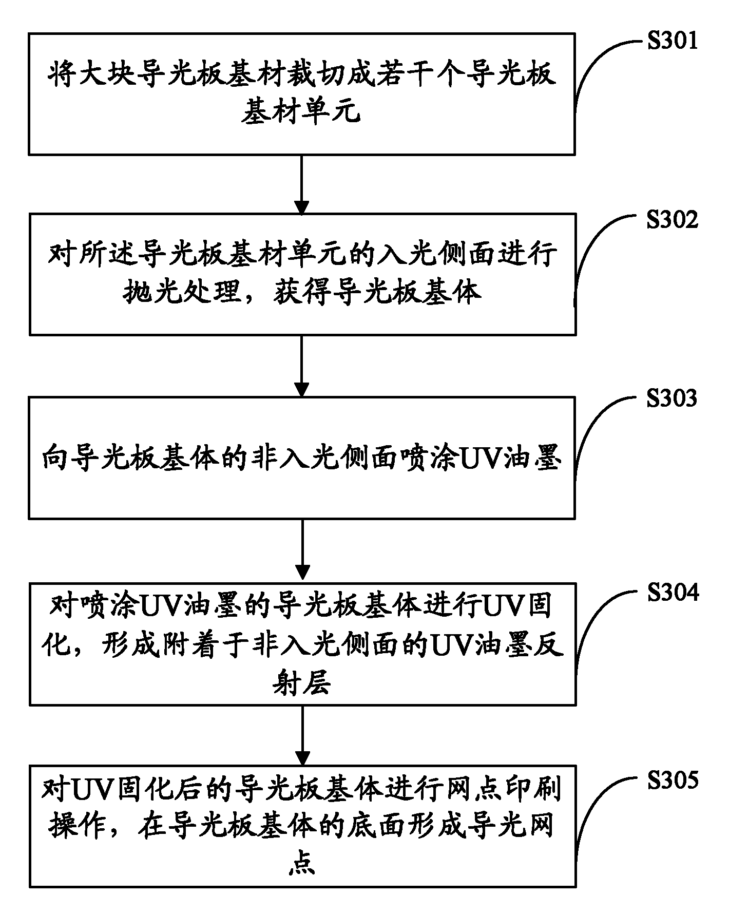
[0048] image 3 The flow chart of the manufacturing method of the light guide plate provided by the third embodiment of the present invention is shown, and for the convenience of description, only the parts related to this embodiment are shown.
[0049] The base of the light guide plate in the first embodiment may also be a light guide plate with no light guide dots printed on the bottom surface. At this time, the steps of making the base of the light guide plate may specifically include the following steps:
[0050] In step S301, the bulk light guide plate base material is cut into several light guide plate base material units of required size.
[0051] In step S302, the light-incident side surface of the base unit of the light guide plate is polished to obtain the base of the light guide plate.
[0052] In this step, multiple light guide plate substrate units that have been cut can be stacked and stacked, and then polished.
[0053] After obtaining several laminated light gu...
PUM
| Property | Measurement | Unit |
|---|---|---|
| Thickness | aaaaa | aaaaa |
| Thickness | aaaaa | aaaaa |
| Thickness | aaaaa | aaaaa |
Abstract
Description
Claims
Application Information
 - Generate Ideas
- Intellectual Property
- Life Sciences
- Materials
- Tech Scout
- Unparalleled Data Quality
- Higher Quality Content
- 60% Fewer Hallucinations
Browse by: Latest US Patents, China's latest patents, Technical Efficacy Thesaurus, Application Domain, Technology Topic, Popular Technical Reports.
© 2025 PatSnap. All rights reserved.Legal|Privacy policy|Modern Slavery Act Transparency Statement|Sitemap|About US| Contact US: help@patsnap.com